Wastegate devices for internal combustion engines

A valve device, internal combustion engine technology, applied in the direction of valve device, exhaust gas recirculation, charging system, etc., can solve the problems of increased wear, increased friction, increased adjustment force, etc., and achieve high chemical resistance and good slip performance Effect

Active Publication Date: 2022-05-03
PIERBURG GMBH & CO KG NEUSS
View PDF3 Cites 0 Cited by
  • Summary
  • Abstract
  • Description
  • Claims
  • Application Information

AI Technical Summary

Problems solved by technology

[0005] However, the problem with such a sealing device is that the sleeve made of steel and the ceramic disc are subject to significantly increased wear due to the pressure transmitted by the spring, although mainly a good sealing effect is achieved, which significantly limits this type of seal. Seal Persistence
In addition, ensuing wear also increases the necessary adjusting force, since the friction increases significantly

Method used


Image

  • Wastegate devices for internal combustion engines
  • Wastegate devices for internal combustion engines

Examples


Embodiment Construction

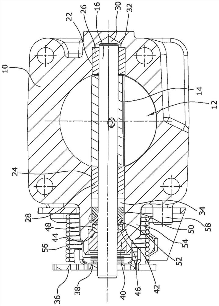
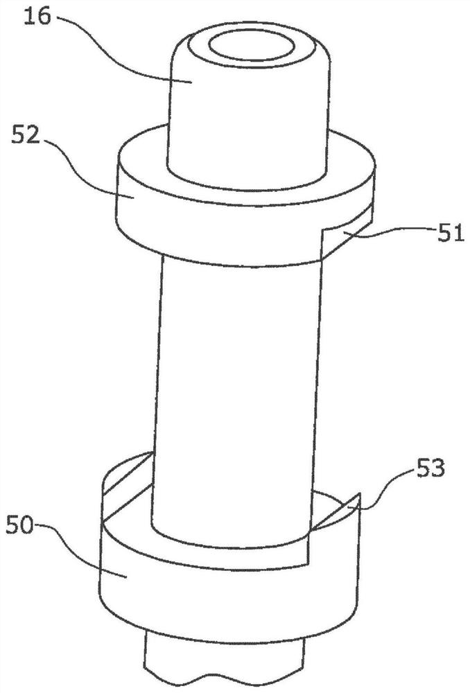
[0025] The wastegate arrangement according to the invention consists of a flow-through housing 10 in which a flow channel 12 is formed. The flow-free cross section of the flow channel 12 is adjusted by turning the valve body 14 in the flow channel 12 . For this purpose, the valve body 14 is fastened to a shaft part 16 , which is mounted centrally on both sides in the flow-through housing 10 , so that the valve body 14 is divided by the shaft part 16 into two valve halves. Opposed bearing receptacles 22 , 24 are formed on the flow-through housing 10 for support, in which bearing receptacles 26 , 28 are respectively arranged, the bearings being designed as radial bearings.

[0026] One end of the shaft part 16 protrudes into a blind hole 30 which serves as the bearing receptacle 22 and in which the bearing 26 is arranged. The bearing 26 rests axially with its one end on a step 32 formed in the blind hole 30 , while the other end of the bearing 26 points toward the flow channel ...


PUM


Abstract

An exhaust gas valve device for an internal combustion engine is known, which has a flow housing (10), a valve body (14), a shaft (16), at least one radial bearing (26, 28), a sealing device (44), The flow housing defines a flow channel (12), the valve body (14) is fixed on the shaft, and the shaft (16) is connected to at least one of the flow housing (10) through the radial bearing. Mounted radially in bearing receptacles (22, 24), the sealing device has a ceramic disk (48) and a sleeve (50) fastened to the shaft (16). In order to reduce the coefficient of friction and wear between the axial bearing and the ceramic disk and to improve the tightness, it is proposed that the axial bearing (40) is fixed in the bore (34) and is made of sintered metal powder of an iron alloy with a high chromium content , and has an austenitic and ferritic composite structure with a carbide alloy composition and a uniformly distributed solid lubricant phase, and is axially loaded relative to a ceramic disk (48) which is free to rotate ground around the shaft (16).

Description

Technical field [0001] The invention relates to an exhaust gas valve device for an internal combustion engine, which has a flow housing, a valve body, a shaft, at least one radial bearing, and a sealing device. The flow housing defines a flow channel, and the valve body is fixed on the The sealing device has a ceramic disk and a sleeve fixed on the shaft. Background technique [0002] Such a wastegate arrangement can be produced, for example, in the form of a butterfly valve and used, for example, as an exhaust gas recirculation flap or an exhaust gas trap flap. [0003] When designing such a wastegate device, special attention must be paid to the seals and axial bearings used, which on the one hand must work as frictionlessly as possible and on the other hand must withstand increased thermal loads and Reliable sealing even in aggressive environments found in the exhaust gas range. The material pair used in the seal is particularly relevant here, since thermal expansion mu...

Claims


Application Information

Patent Timeline
IPC IPC(8): F02D9/04F02D9/10F02M26/65F02M26/70F16K1/20
CPCF16K1/2028F02D9/04F02D9/106F02M26/65F02M26/70
Inventor S.汉布洛克D.卡玛丽斯R.埃克豪特K.冯德比克R.罗伊尔J.拉杰夫斯基
Owner PIERBURG GMBH & CO KG NEUSS
Why Eureka
Try Eureka