
Exhaust turbocharger with bypass valve

An exhaust gas turbine and supercharger technology, which is applied in gas turbine devices, machines/engines, jet propulsion devices, etc., can solve the problems of small mass and small structure space, and achieve the effect of small power consumption requirements

Active Publication Date: 2015-11-25
VOLKSWAGEN AG
View PDF6 Cites 0 Cited by
  • Summary
  • Abstract
  • Description
  • Claims
  • Application Information

AI Technical Summary

Problems solved by technology

[0007] Against this background, the technical problem to be solved by the present invention is to design an exhaust gas turbocharger of the type mentioned at the outset in such a way that a bypass valve in the bypass channel of the turbine of the exhaust gas turbocharger can be provided with a Inexpensive control means with a low power consumption, in particular with a small installation space and / or low mass

Method used


Image

  • Exhaust turbocharger with bypass valve
  • Exhaust turbocharger with bypass valve
  • Exhaust turbocharger with bypass valve

Examples


Embodiment Construction

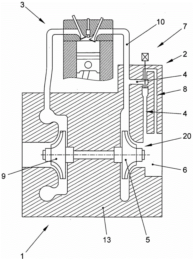
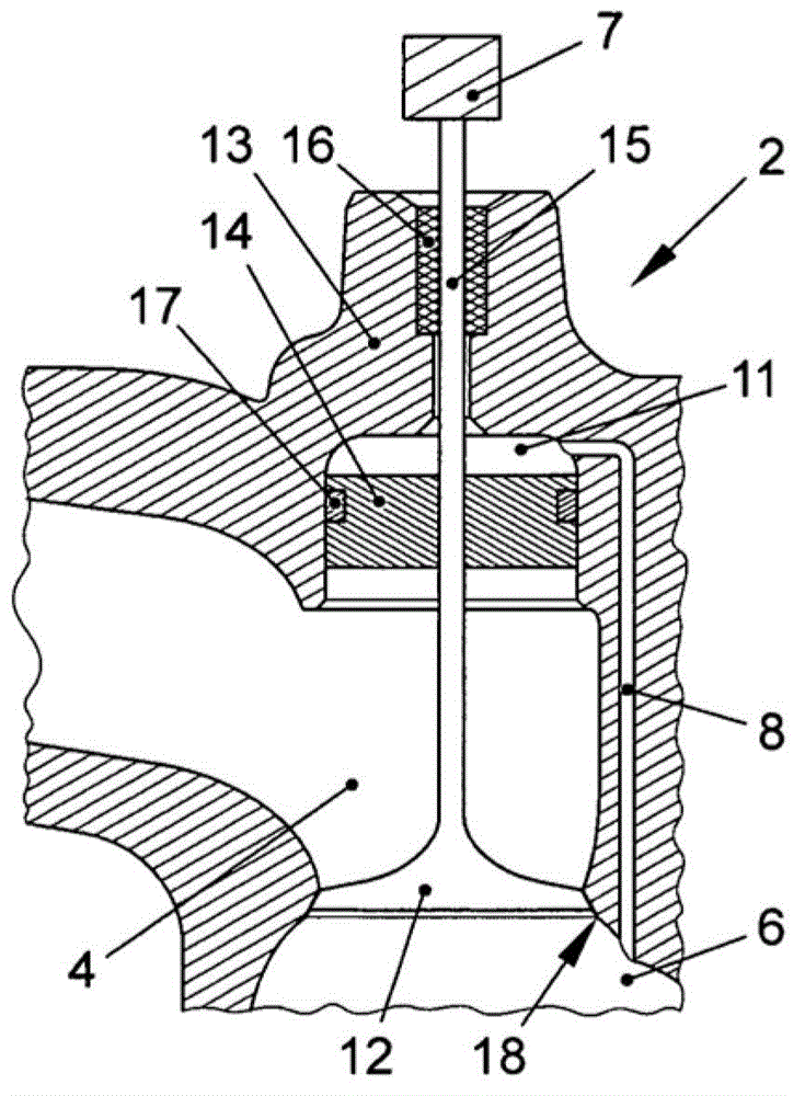
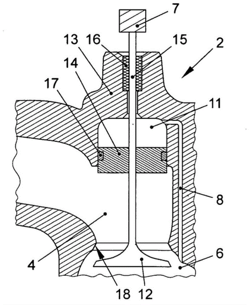
[0025] figure 1 An exhaust gas turbocharger 1 of an internal combustion engine 3 is shown. The exhaust gas turbocharger 1 has a compressor 9 on the intake side of the internal combustion engine and a turbine 5 on the exhaust side of the internal combustion engine. A bypass channel 4 is provided in the housing 13 of the exhaust gas turbocharger 1 for bypassing the turbine 5 . The bypass channel 4 connects the exhaust gas pressure line 10 to the outlet section 6 of the turbine. A bypass valve 2 for closing the bypass channel 4 is arranged in the bypass channel 4 . The embodiment shown has a section of bypass channel 4 , which can also be referred to as a branch of exhaust gas pressure line 10 , which is delimited by bypass valve 2 and exhaust gas pressure line 10 . A compensating line 8 connects the recess in the region of the bypass valve 2 to the outlet section 6 , so that the same pressure always prevails in the recess as in the outlet section 6 .

[0026] figure 2 and ...


PUM


Abstract

An exhaust-gas turbocharger is embodied with a bypass valve which is disposed in a bypass duct of a turbine between an exhaust-gas pressure line and an outlet cross section of the turbine of the exhaust-gas turbocharger and which is connected to an actuating device for controlling the throughput of exhaust-gas through the bypass duct. Through the bypass valve, a partial flow of the exhaust-gas can be guided past the turbine on demand. The bypass valve has a valve head and a valve stem. The bypass valve is axially movably held with the valve stem. The valve head, in a closed state of the bypass valve, can be placed against a valve seat in order to close the bypass duct in a gas-tight and pressure-tight manner. The side of the valve head that is connected to the valve stem faces the exhaust-gas pressure line.

Description

technical field [0001] The invention relates to an exhaust gas turbocharger for an internal combustion engine which is designed with a bypass valve which is arranged in the outlet section of the turbine of the exhaust gas turbocharger in relation to the exhaust gas In the turbine bypass passage between the pressure conduits. Background technique [0002] During operation of the internal combustion engine with the exhaust gas turbocharger, a bypass channel for the turbine of the exhaust gas turbocharger selectively guides a partial flow of exhaust gas past the turbine. For this purpose, a bypass valve, also known as a wastegate valve, for opening or closing the bypass channel is arranged in the bypass channel. The bypass valve consists of a valve disc and a valve stem. The valve disc is pressed against the valve seat when the bypass valve is closed. When there is a load demand on the internal combustion engine, the bypass valve closes and is pressed against the valve seat ...

Claims


Application Information

Patent Timeline
IPC IPC(8): F02B37/18F01D17/14
CPCF02B37/186F02B37/183F02C6/12F02C9/18F05D2220/40Y02T10/144Y10T137/7785Y02T10/12F01D17/14F02B37/18
Inventor J.库尔梅耶D.哈格尔斯坦E.利珀特
Owner VOLKSWAGEN AG
Learn More