Efficient large-flux fixed valve tray
A fixed-valve, high-throughput technology, applied in the direction of dissolution, distillation and separation, chemical instruments and methods, etc., can solve the problem of reducing the tray processing capacity and operating flexibility, reducing the operating flexibility of the tray, and reducing the mass transfer efficiency of the tray To achieve the effect of improving mass transfer efficiency and operating flexibility, improving processing capacity and operating flexibility, and improving mass transfer efficiency of trays
- Summary
- Abstract
- Description
- Claims
- Application Information
AI Technical Summary
Problems solved by technology
Method used
Image

Examples
Embodiment 1
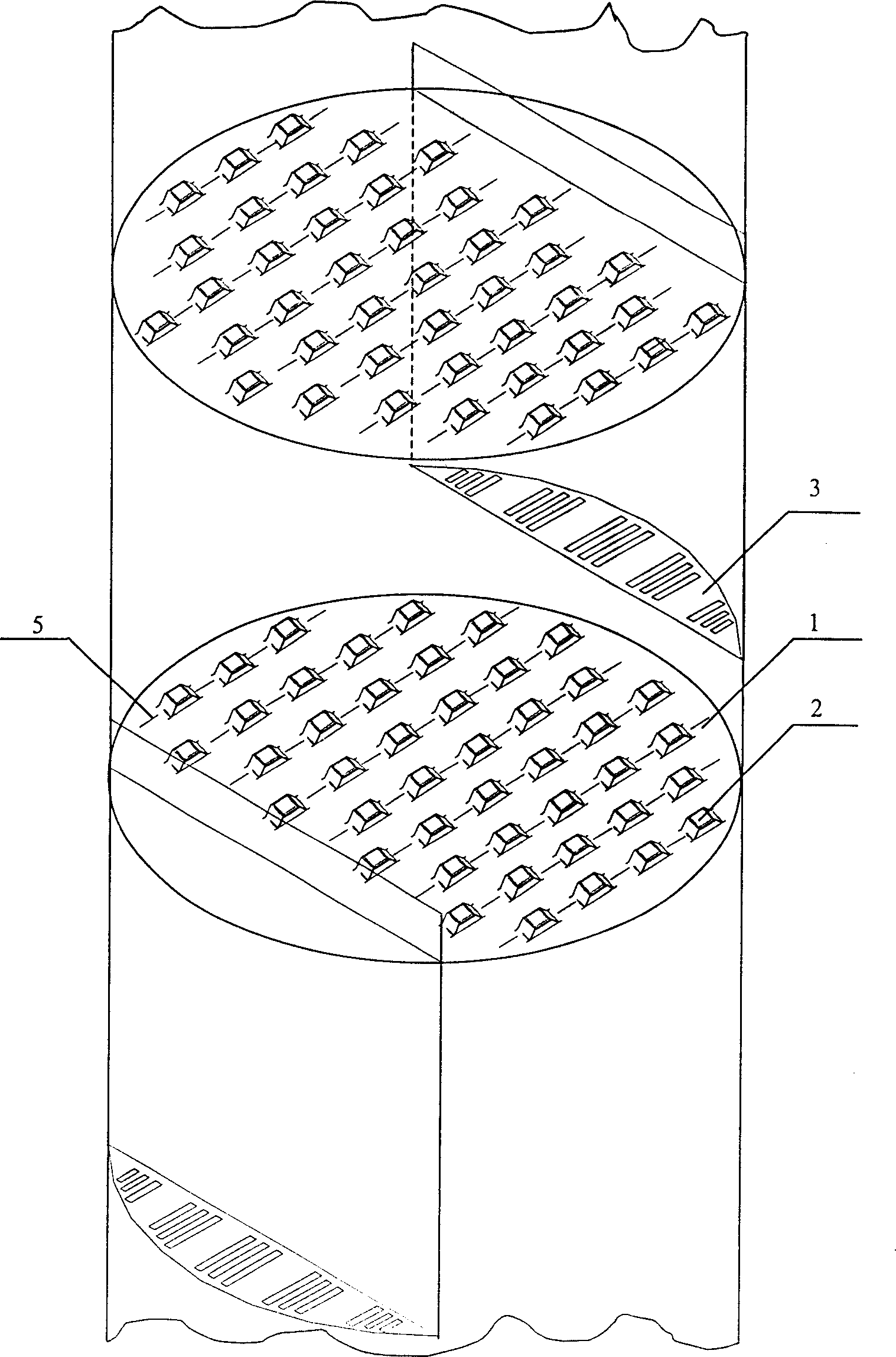
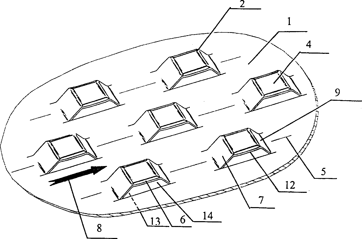
[0020] The high-efficiency and large-flux fixed-valve tray is characterized in that the high-efficiency and large-flux fixed-valve tray is composed of a tray 1, a fixed valve 2 and a downcomer 3. The fixed valve 2 is formed by direct punching of the tray 1 body, and the fixed valve 2 is composed of fixed valve face 4, liquid-facing valve leg 7 and back-liquid valve leg 9, fixed valve face 4 is connected with tray 1 through liquid-facing valve leg 7 and back-liquid valve leg 9, and fixed valve face 4 has The fixed valve flange 6 bent downwards, the downward bending angle of the fixed valve flange 6 is 15°, the fixed valve flange edge 12 of the fixed valve flange 6 is 3 to 10mm away from the plate surface of the tray 1, and the fixed valve 2 After the tray 1 is punched out, the fixed valve hole 13 is formed on the tray 1, the fixed valve flange edge 12 of the fixed valve flange 6, the edge of the liquid-facing valve leg 7, the edge of the back-liquid valve leg 9 and the fixed val...
Embodiment 2
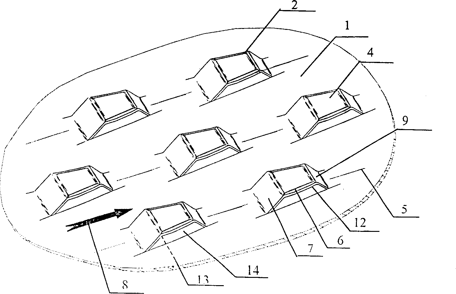
[0022] The high-efficiency and large-flux fixed-valve tray is characterized in that the high-efficiency and large-flux fixed-valve tray is composed of a tray 1, a fixed valve 2 and a downcomer 3. The fixed valve 2 is formed by direct punching of the tray 1 body, and the fixed valve 2 is composed of fixed valve face 4, liquid-facing valve leg 7 and back-liquid valve leg 9, fixed valve face 4 is connected with tray 1 through liquid-facing valve leg 7 and back-liquid valve leg 9, and fixed valve face 4 has The fixed valve flange 6 bent downwards, the downward bending angle of the fixed valve flange 6 is 35°, the fixed valve flange edge 12 of the fixed valve flange 6 is 3-10mm away from the plate surface of the tray 1, and the fixed valve 2 After the tray 1 is punched out, the fixed valve hole 13 is formed on the tray 1, the fixed valve flange edge 12 of the fixed valve flange 6, the edge of the liquid-facing valve leg 7, the edge of the back-liquid valve leg 9 and the fixed valve ...
Embodiment 3
[0024]The high-efficiency and large-flux fixed-valve tray is characterized in that the high-efficiency and large-flux fixed-valve tray is composed of a tray 1, a fixed valve 2 and a downcomer 3. The fixed valve 2 is formed by direct punching of the tray 1 body, and the fixed valve 2 is composed of fixed valve face 4, liquid-facing valve leg 7 and back-liquid valve leg 9, fixed valve face 4 is connected with tray 1 through liquid-facing valve leg 7 and back-liquid valve leg 9, and fixed valve face 4 has The fixed valve flange 6 bent downwards, the downward bending angle of the fixed valve flange 6 is 50°, the fixed valve flange edge 12 of the fixed valve flange 6 is 3 to 10 mm away from the plate surface of the tray 1, and the fixed valve 2 After the tray 1 is punched out, the fixed valve hole 13 is formed on the tray 1, the fixed valve flange edge 12 of the fixed valve flange 6, the edge of the liquid-facing valve leg 7, the edge of the back-liquid valve leg 9 and the fixed val...
PUM
 Abstract
Description
Claims
Application Information
 - Generate Ideas
- Intellectual Property
- Life Sciences
- Materials
- Tech Scout
- Unparalleled Data Quality
- Higher Quality Content
- 60% Fewer Hallucinations
Browse by: Latest US Patents, China's latest patents, Technical Efficacy Thesaurus, Application Domain, Technology Topic, Popular Technical Reports.
© 2025 PatSnap. All rights reserved.Legal|Privacy policy|Modern Slavery Act Transparency Statement|Sitemap|About US| Contact US: help@patsnap.com