


Quick Research
Generate reliable direction feasibility study reports for your R&D in just a few steps.

Technical Q&A
Discover and master advanced knowledge NOW. Basics, ideas, possibilities, all at once.

Find Solutions
As an expert in R&D theories, this can generate solutions to your technical problems instantly.

Evaluate Feasibility
Analyze your overall solution with one click, know your potential R&D risks in advance.

Monitor Landscape
Get weekly tech updates, stay abreast of the latest tech innovations and key insights.
Device with multiple packing machines sharing pipe sticking machine
A packaging machine and tube sticking machine technology, applied in the direction of packaging machines, packaging, transportation and packaging, etc., can solve the problems of large area occupation, repeated investment, waste of tube sticking machines, etc., to reduce investment costs, ensure continuity, improve The effect of production efficiency
- Summary
- Abstract
- Description
- Claims
- Application Information
AI Technical Summary
Problems solved by technology
Method used
Image

Examples
Embodiment 1
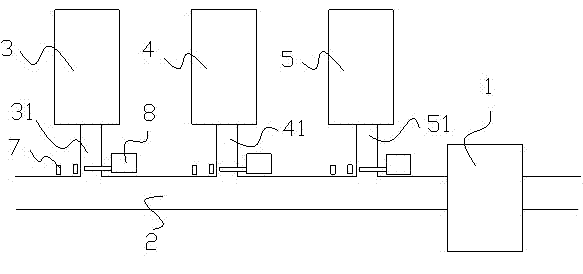
[0014] Such as figure 1 , The device for multiple packaging machines sharing the tube applicator of the present invention includes a conveyor belt 2 connected to the tube applicator 1, the discharge channel 31 of the packaging machine 3, the discharge channel 41 of the packaging machine 4, and the packaging machine 5 The discharge channel 51 is connected to the conveyor belt 2 at intervals. The connection between the discharge channel 31 of the packaging machine 3 and the conveyor belt 1 is provided with a sensor 7 for detecting whether the connection is sufficient for placing a packaging box. The discharging channel 31 is provided with a cutting device 8 controlled according to the signal of the sensor 7. The packaging machine 3, the packaging machine 4 and the packaging machine 5 are all located on the same side of the conveyor belt 2. This embodiment can be used when the width of the workshop where the packaging machine and the tube sticking machine are placed is insufficien...
Embodiment 2
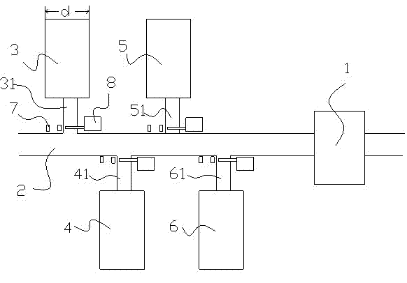
[0016] Such as figure 2 , Multiple packaging machines share the device of the tube applicator, including a conveyor belt 2 connected to the tube applicator 1, the discharge channel 31 of the packaging machine 3, the discharge channel 41 of the packaging machine 4, and the discharge channel of the packaging machine 5 51. The discharge channel 61 of the packaging machine 6 is connected to the conveyor belt 2 at intervals, and the connection between the discharge channel 31 of the packaging machine 3 and the conveyor belt 1 is provided with a sensor for detecting whether the connection is sufficient to place a packaging box. 7. The discharge channel 31 of the packaging machine 3 is provided with a cutting device 8 controlled by the signal of the sensor 7. The packaging machine 3, the packaging machine 4, the packaging machine 5, and the packaging machine 6 are arranged on both sides of the conveyor belt 2 at a cross interval. When the width d of the discharge channel of the pack...
PUM
 Abstract
Description
Claims
Application Information
 - R&D Engineer
- R&D Manager
- IP Professional
- Industry Leading Data Capabilities
- Powerful AI technology
- Patent DNA Extraction
Browse by: Latest US Patents, China's latest patents, Technical Efficacy Thesaurus, Application Domain, Technology Topic, Popular Technical Reports.
© 2024 PatSnap. All rights reserved.Legal|Privacy policy|Modern Slavery Act Transparency Statement|Sitemap|About US| Contact US: help@patsnap.com