AES disinfection channel spraying method

A channel and disinfection solution technology, which is applied in the direction of disinfection, sanitary equipment for toilets, water supply devices, etc., can solve the problems of insufficient spraying methods, narrow application range, secondary pollution, etc., achieve efficient and stable spraying efficiency, improve disinfection protection, The effect of improving airtightness

Pending Publication Date: 2022-03-25
安徽同净枫翎新材料科技有限公司 +1
View PDF0 Cites 0 Cited by
  • Summary
  • Abstract
  • Description
  • Claims
  • Application Information

AI Technical Summary

Problems solved by technology

[0002] In our living environment, the most difficult pollutants to deal with, such as formaldehyde, pesticides, phenol, etc., are all organic matter, while traditional pollution control technologies can only absorb and transfer pollutants, but cannot eradicate them, and the use of chemical additives will lead to serious pollution. The principle of photocatalytic technology is to use nano-titanium dioxide as a photocatalyst, which does not react under light, and can automatically and completely decompose organic pollutants into carbon dioxide and water from the molecular level. Photocatalytic technology not only degrades completely, but also The process is similar to photosynthesis, it can happen when there is light, and the produced substances return to the natural cycle
[0003] Photocatalytic technology is recognized as the cleanest and most thorough environmental protection technology in the world, but the characteristics of nano photocatalyst to degrade organic matter make it also cause photodegradation and corrosion to organic carriers, and can only be loaded on the surface of inorganic solids such as ceramics and glass. The application range of the loading method is narrow, the photocatalytic effect is weak, and the conditions and functions for degrading high-concentration organic pollutants are basically lost. The limitation of the photocatalyst on the carrier is that the photocatalytic technology cannot be practical in the field of environmental protection since it was first discovered 50 years ago. The root cause of the breakthrough is the new core-shell structure photocatalyst loading technology, which locks titanium dioxide nanoparticles in a cage made of inorganic materials through nano-preparation technology, so that the photocatalyst can perform photocatalysis through the cage, maintain its activity, and avoid In order to directly contact the organic carrier and effectively prevent the occurrence of photocorrosion, this technology breaks through the limitation of the photocatalyst on the carrier, allowing the photocatalyst to be loaded on almost any carrier
[0004] The AES disinfection channel is a kind of disinfection protection equipment based on the above-mentioned new core-shell structure photocatalyst loading technology. If the spray method used in the existing disinfection channel adopts the double-sided spraying method, it often needs to set up an independent raw material supply device, and During the spraying process, the mist liquefaction phenomenon is relatively serious, which requires repeated atomization, resulting in a large consumption of energy, and at the same time, the liquid formed by liquefaction needs to be collected again. The traditional spraying method is not efficient and stable enough.

Method used


Image

  • AES disinfection channel spraying method
  • AES disinfection channel spraying method
  • AES disinfection channel spraying method

Examples


Embodiment 1

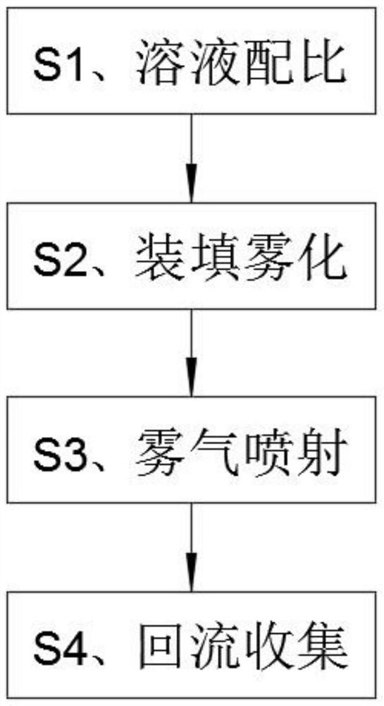
[0038] Such as Figure 1-4 As shown, a AES disinfection channel spray method is characterized in that the following steps are included:

[0039] S1, solution ratio: mix the AES new material with water for 1: 99, then stirred 30s, and the disinfectant solution is obtained;

[0040] S2, filling fitting: Add the sterilization solution to the reservoir 4 of the water tank 4 inside the dust collecting passage by the inlet hole 404, and the liquid level height is located on the lower side of the lateral separator 18, and the water pump 11 and the water pipe 12 will be stored The solution in the liquid zone is pumped into the atomization zone, and the atomizer 20 is discharged from the fog tube 15 after atomizing the solution in the pressure of the fan 16.

[0041] S3, fog injection: fog sequentially passes through the left guiding box body 5, connect the tube 602, the horizontal pipe 603, and the right guiding box body, forms both sides of the spray in the channel by the spray groove 201...

Embodiment 2

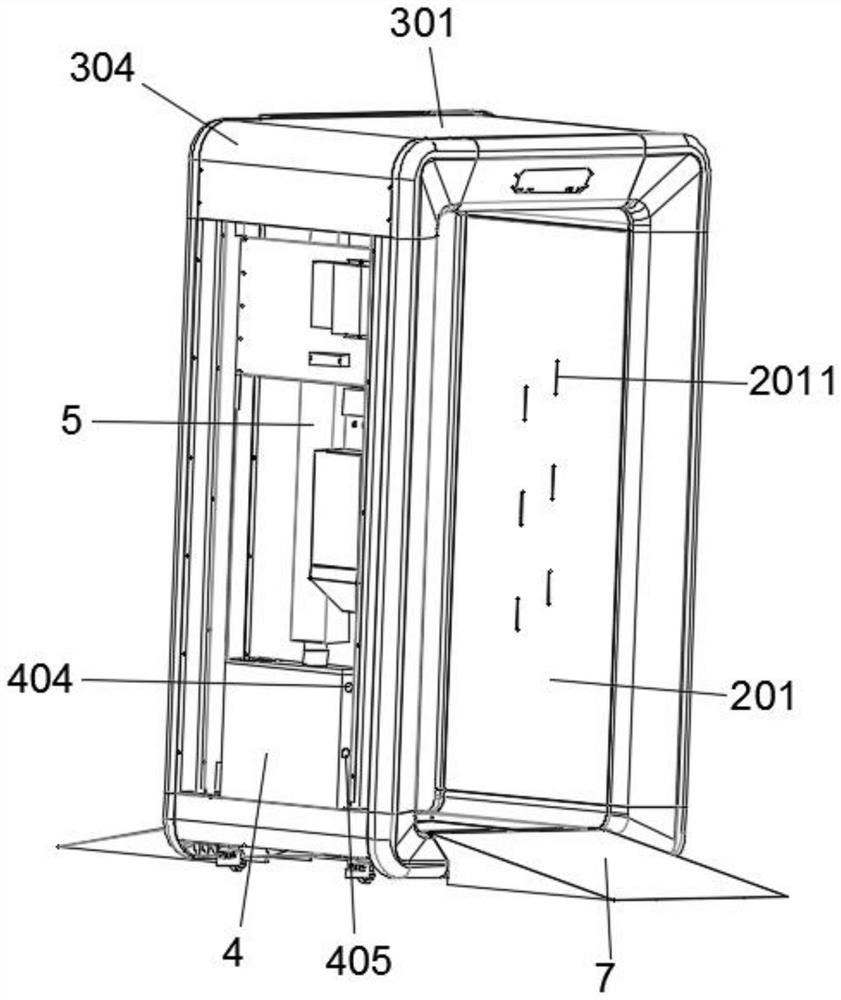
[0046] On the basis of Example 1, ifFigure 1-7 The integrated channel described in step S2, includes a frame 1, the frame 1 including block 101 and a vertical rod 102, the square frame 101 is provided with two groups and up and down, two sets of square block 101 There is a fixed connection between the rod 102;

[0047] The inner plate 2 includes an inner plate 201, an inner top plate 202, an inner bottom plate 203, and an inner arc plate 204, and the upper side of the side frame 101 is fixedly mounted with inner bottom plate 203, and the inner bottom plate 203 Since the internal arc plate 204 is fixed, the upper side of the square frame 101 is fixedly mounted, and the inner arc plate 204 is fixed, and the inner arc plate 204 is fixed, and the inner side plate 201 respectively corresponds to an arc plate, respectively. 204 fixed connection;

[0048] The outer plate 3 includes a top plate 301, an outer plate 302, an outer substrate plate 303, and an outer arc plate 304, and the lowe...

Embodiment 3

[0061] On the basis of the above embodiments, such as Figure 8-11 Indicated;

[0062] The tank 4 is fixed to the top of which is attached to the top of the water tank 4, from left to right, the air outlet 402, the air outlet 402, and the mounting port 403, the water tank 4, front and rear side wall, two side walls, fixed mounting There is a guide plate 17, the guiding plate 17 is inclined toward the air outlet 401 side, and the upper side is fixed to the upper side of the connecting plate 14, and the sealing plate 14 is located on the upper side of the inlet 401. Fan 16 is attached to the opening, the sealing plate 14 is located on the upper side of the air opening 402, and the fog tube 15 is inserted inside the water tank 4;

[0063] The inner left side wall of the water tank 4 is fixedly mounted having a lateral partition 18 and a longitudinal separator 19, and the lateral partition 18 and the longitudinal separator 19 divided the water tank 4 into an atomizing region and a rese...


PUM


Abstract

The invention relates to the technical field of disinfection protection, and discloses an AES disinfection channel spraying method, which comprises the following steps: S1, solution proportioning: mixing an AES new material and water according to a ratio of 1: 99, and stirring for 30 s to prepare a disinfection solution; the disinfection solution is added into a liquid storage area of a water tank in a dust collection channel through a water inlet hole, the solution in the liquid storage area is pumped into an atomization area through a water pump and a water pipe, and mist is discharged out of the water tank from a mist outlet pipe under the pressure action of a fan after the solution is atomized by an atomizer; s3, mist spraying, wherein mist sequentially penetrates through a left mist guide box body, a communicating pipe, a transverse pipe and a right mist guide box body under the action of air pressure; and S4, backflow collection: then the water flows back to a liquid storage area of the water tank through a corrugated water pipe and a backflow hole. A reciprocating circulating spraying operation is formed, and the whole spraying process does not need human interference and can be continuously carried out, so that the high spraying efficiency is ensured, and the disinfection and protection effects are improved.

Description

Technical field: [0001] The present invention relates to the field of disinfection and protection, and more particularly to a AES disinfection channel spray method. Background technique: [0002] In our live environment, the most difficult contaminants, such as formaldehyde, pesticides, phenol, etc. are all organic, while traditional pollution control technology can only adsorb and transfer pollutants, can not eradicate, using chemical additives can cause serious The secondary pollution, the principle of photocatalytic technology is that the nano-titanium dioxide is a light tie body, which does not react itself under the light, automatically decomposes the organic contaminant from the molecular level into carbon dioxide and water, but the photocatalytic technology is not only degraded, but also The process is similar to photosynthesis, and there is light to occur, and the resulting substance is returned to the natural cycle. [0003] The world is recognized as the cleaning and mo...

Claims


Application Information

Patent Timeline
Patent Type & Authority Applications(China)
IPC IPC(8): A61L2/22A61L2/26
CPCA61L2/22A61L2/26A61L2202/15A61L2202/121
Inventor 陈乃科
Owner 安徽同净枫翎新材料科技有限公司
Why Eureka
Try Eureka