Method of concurrently burning aluminate, bauxite and aluminium sulfide gel material for generating boiler

An iron aluminate and power generation boiler technology, applied in the field of building materials, can solve the problems of short firing time, unfavorable clinker mineral formation, insufficient clinker formation time, etc., to simplify the production process, improve the sulfur fixation effect, and improve the product. the effect of strength

Inactive Publication Date: 2005-03-02
DENGFENG ELECTRICITY GRP
View PDF0 Cites 0 Cited by
  • Summary
  • Abstract
  • Description
  • Claims
  • Application Information

AI Technical Summary

Problems solved by technology

However, since the main business of the boiler is power generation, the addition of admixtures is limited and cannot meet the composition requirements of Portland cement; at the same time, the boiler is not an ideal sintering device for complex silicate clinker (the sintering time is short 3 -5 seconds, the clinker formation time is not enough, and the suspended powder is difficult to agglomerate, which is not conducive to the formation of clinker minerals)
Despite years of experimental research, so far, there is no successful precedent for burning Portland cement in power boilers at home and abroad.

Method used


Image

  • Method of concurrently burning aluminate, bauxite and aluminium sulfide gel material for generating boiler
  • Method of concurrently burning aluminate, bauxite and aluminium sulfide gel material for generating boiler
  • Method of concurrently burning aluminate, bauxite and aluminium sulfide gel material for generating boiler

Examples


Embodiment 1

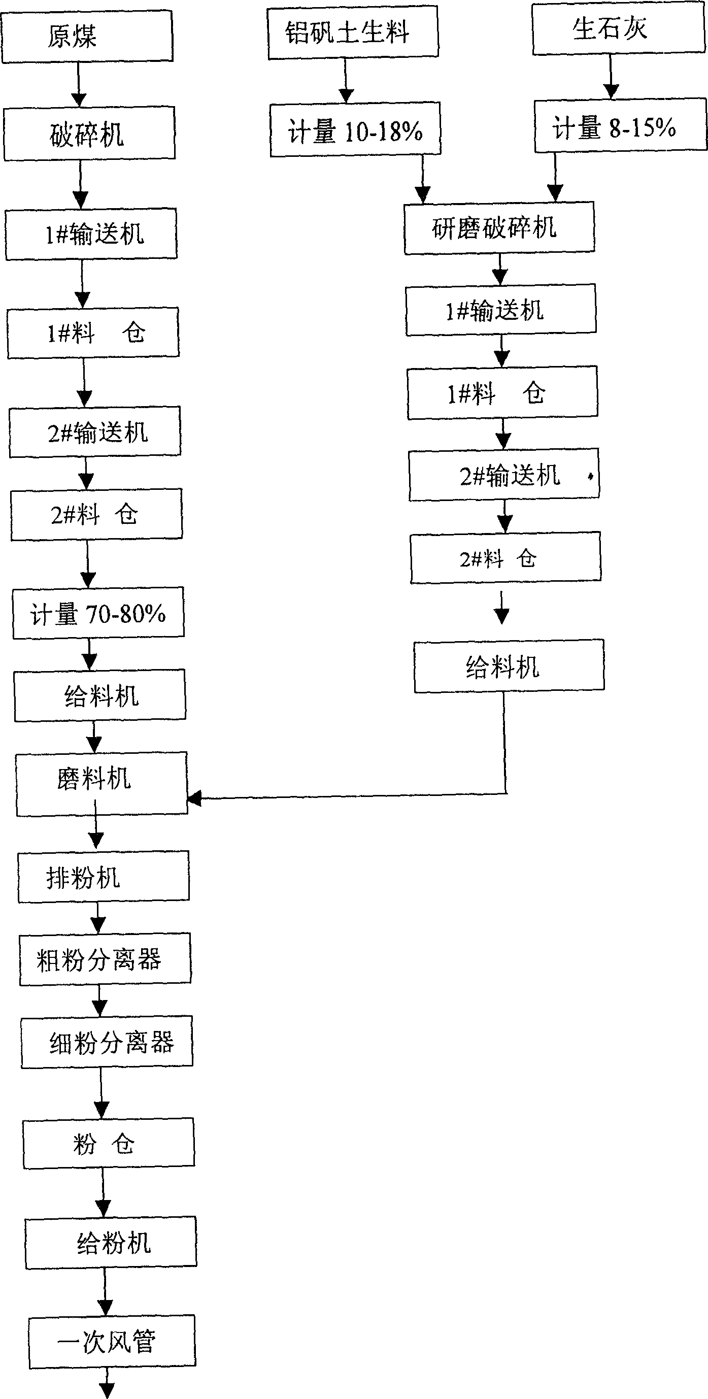
[0023] a. Raw coal (the ash content of coal is not higher than 35%) - sent to the crusher - via 1# conveyor - to 1# raw material warehouse - through 2# conveyor - to #2 raw material warehouse - Get raw coal (by weight) 70-80% into the feeder;

[0024] b. Take 10-18% of bauxite raw meal and 8-15% of quicklime through automatic metering device (by weight ratio)—send it to the grinding crusher—via 1# conveyor—to 1# raw material bin—pass 2# conveyor - to #2 raw material bin - enters the feeder;

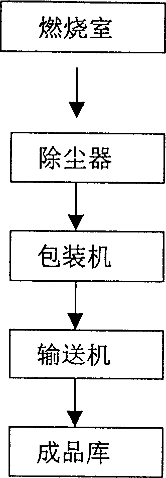
[0025] c. Send a and b to the grinding machine through the feeder—powder discharge fan—coarse powder separator—fine powder separator—to the coal powder bin—through the powder feeder—powder falling Pipe—Enter the primary air duct—carried into the furnace by the primary air—after burning, the ash particles pass through the electrostatic precipitator—packaging machine—conveyor—finally to the finished product warehouse.

[0026] The above process should be carried out under the condition th...

Embodiment 2

[0028] Take 70-80% of raw coal (the ash content of coal is not higher than 35%), 10-18% of bauxite raw meal, and 8-15% of quicklime through an automatic metering device (by weight)—feed into the crusher—through 1 #Conveyor - to 1# raw material bin - through 2# conveyor - to 2# raw material bin - into the feeder - into the existing coal mill - powder exhaust fan - coarse powder separator ——fine powder separator——to coal powder bin——through powder feeder——powder falling pipe——into the primary air duct——carried into the furnace by the primary air——after combustion, the ash particles pass through the electrostatic precipitator——package Machine - Conveyor - Finally to the finished product warehouse.

[0029] The above process should be carried out under the condition that the load is not lower than 70%. This embodiment makes full use of the existing technological process of the power plant, and saves a set of grinding and conveying system compared with Embodiment 1, saving one-tim...


PUM


Abstract

The invention relates to a method for producing gelatinization materials of aluminate, ferroaluminate and thioaluminate by using power generation boiler, which it is characterized by that 70-80% of raw coal, 10-18% of bauxite raw material and 8-15% of caustic lime are mixed, ground and homogenized, then the obtained mixed material is fed into powder-falling pipe, passed through air passage and fed into combustion chamber, after combustion the ash granules are passed through electrostatic precipitator to obtain the finished product, such as aluminate, ferroaluminate and thioaluminate gelatinization materials.

Description

(1) Technical field [0001] The invention relates to the field of building materials, in particular to a method for utilizing a power generation boiler to simultaneously burn aluminate, iron-aluminate and sulphoaluminate cementitious materials. The products produced by this method can be used as cement for asbestos tiles, GRC cement (that is, fiber-reinforced cement), and can also be used as a variety of cement or concrete admixtures, masonry cement, and road cushion-sandy soil. (2) Background technology [0002] At present, the fuel used in my country's power plant boilers is mainly coal, which is generally first ground into coal powder, and then sent to the furnace for combustion. Specifically, the coal falling from the coal bunker is sent to the coal mill through the coal feeder to be ground into coal powder, and the coal is dried with hot air during the grinding process. The blower sends the cold air to the air preheater at the end of the boiler, where the cold air is he...

Claims


Application Information

Patent Timeline
Patent Type & Authority Patents(China)
IPC IPC(8): C04B7/00C04B7/32
Inventor 程明都武长富韩建政王金涛李新涛贾让权杜艮安张端奇陈五晓吴新立王金超吴新源范现召
Owner DENGFENG ELECTRICITY GRP
Why Eureka
Try Eureka