Cavity filter

A cavity filter and filter technology, applied in waveguide devices, resonators, circuits, etc., can solve problems such as surface finish and flatness defects on the bottom surface, achieve good parallelism, and simplify fine-tuning

Inactive Publication Date: 2004-11-03
UNWIRED PLANET
View PDF0 Cites 0 Cited by
  • Summary
  • Abstract
  • Description
  • Claims
  • Application Information

AI Technical Summary

Problems solved by technology

The electrical contact between the center conductor and the bottom of the cavity is formed by the bottom surface around the screw, which in this known construction may be deficient in surface finish and flatness

Method used


Image

  • Cavity filter
  • Cavity filter
  • Cavity filter

Examples


Embodiment Construction

[0021] DETAILED DESCRIPTION OF THE PREFERRED EMBODIMENT

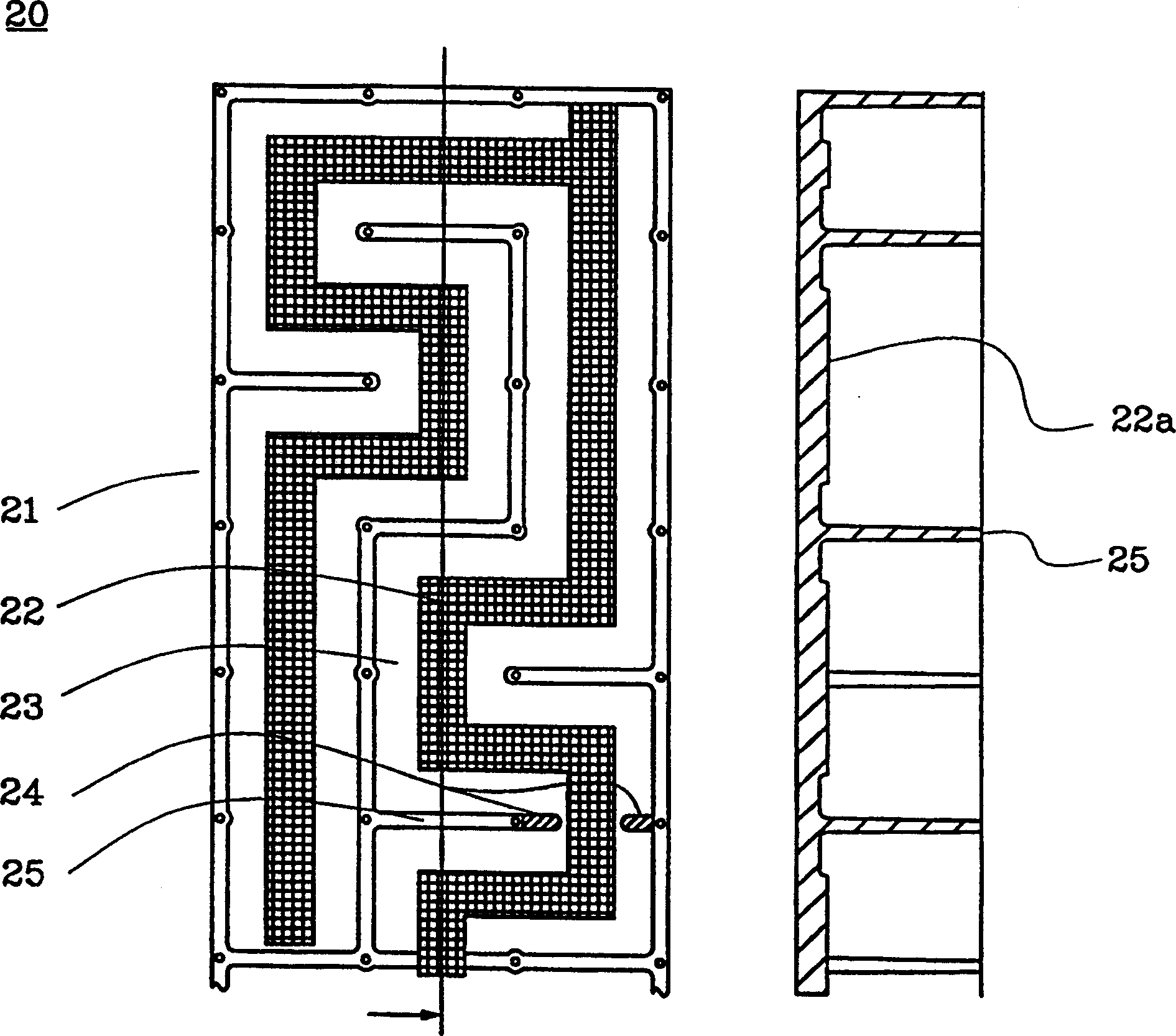
[0022] figure 2 is a top sectional view of the first embodiment of the cavity filter of the present invention. The filter 20 comprises a body 21 and a cavity bottom 23 in which a groove 22 for fixing the central conductor is arranged. In the embodiment shown, the groove is raised to a position 1-2 mm above the bottom 23 of the cavity and runs through the cavity or cavities delimited by the side walls 25 .

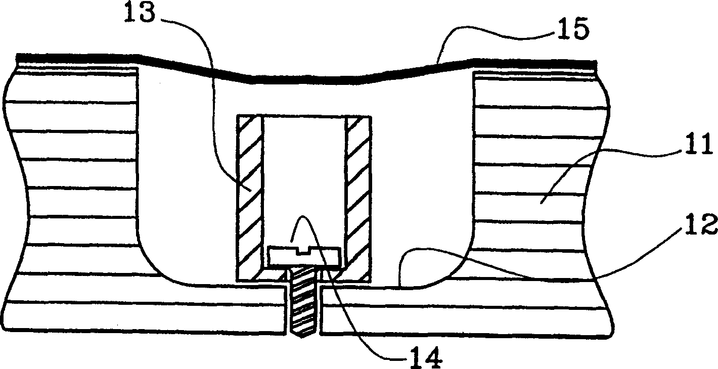
[0023] Figure 5 is a sectional view showing a part of the cavity filter of the present invention and a central conductor 53 according to an embodiment of the present invention. The cavity filter comprises a body 51 and a cavity covered by a trim plate 55 . exist Figure 5 In the illustrated embodiment, the center conductor 53 is fixed in a groove 52 above the bottom of the cavity, which groove corresponds to figure 2 Groove 22 shown in. The groove 52 is machined to have a very flat surface and is slightly w...


PUM


Abstract

The present invention relates to a cavity filter (20) that includes a plurality of centre conductors which are mounted on an elevation (22) that extends along several cavities. The elevation can be produced on the bottom surface (23) of the cavity body (21) to a high degree of flatness in one single working step, and a precise measurement and precise parallelity between said bottom surface and the side walls (25) of the cavities can be obtained.

Description

field of invention [0001] The present invention relates to an improved cavity filter which can be easily manufactured and which can be machined to a high degree of precision. More specifically, the invention relates to the specific design of the cavity bottom of such a filter. Background of the invention [0002] When constructing and manufacturing high-frequency filters for radio base stations, it is necessary to construct the filter as a so-called cavity filter consisting of a plurality of cavities, with a single central conductor or multiple central conductors in each cavity. conductor. These filters are used, for example, in GSM mobile telephone base stations at frequencies 900 MHz and 1800 / 1900 MHz. [0003] When the filter is tuned to a quarter wavelength of the received signal, each cavity and its single / multiple center conductors act as an oscillating circuit which can be composed of an inductive part L and a capacitive part C parallel oscillator circuit to provid...

Claims


Application Information

Patent Timeline
IPC IPC(8): H01P1/205H01P7/04
CPCH01P1/205H01P7/04
Inventor B·U·E·亨宁松M·利卡马尔
Owner UNWIRED PLANET
Why Eureka
Try Eureka