


Quick Research
Generate reliable direction feasibility study reports for your R&D in just a few steps.

Technical Q&A
Discover and master advanced knowledge NOW. Basics, ideas, possibilities, all at once.

Find Solutions
As an expert in R&D theories, this can generate solutions to your technical problems instantly.

Evaluate Feasibility
Analyze your overall solution with one click, know your potential R&D risks in advance.

Monitor Landscape
Get weekly tech updates, stay abreast of the latest tech innovations and key insights.
Intelligent processing equipment for laminated glass with glue overflow prevention mechanism
A laminated glass, intelligent processing technology, applied in the improvement of windows/doors, lamination auxiliary operations, chemical instruments and methods, etc., can solve the problem of insufficient uniform filling of laminated glass glue, and reduce the glue sticking to pollutants. The probability of reducing the workload and avoiding the effect of pollution
- Summary
- Abstract
- Description
- Claims
- Application Information
AI Technical Summary
Problems solved by technology
Method used
Image

Examples
Embodiment 1
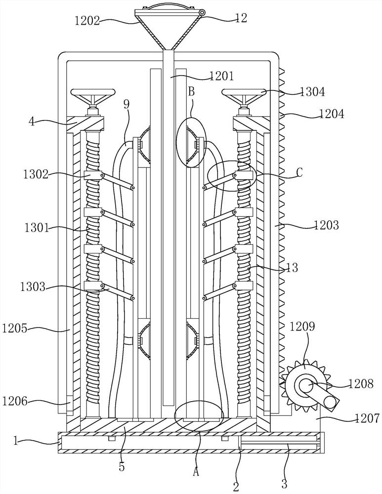
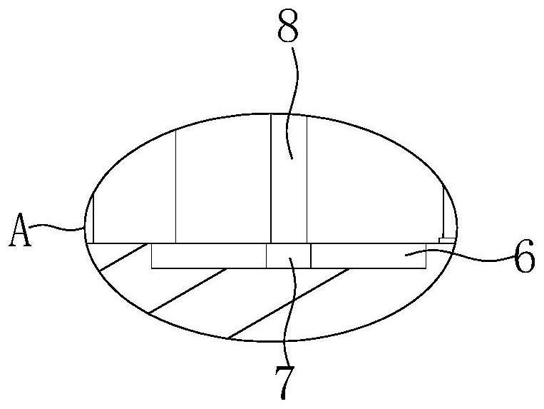
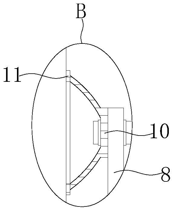
[0030] see Figure 1-7 , the present invention provides a technical solution: an intelligent processing equipment for laminated glass with an anti-overflow glue mechanism, including a hollow plate 1, a glue injection mechanism 12 and an overflow prevention mechanism 14, the hollow plate 1 is provided with a sealing plate 2 inside, and the hollow plate 1 is provided with a sealing plate 2. A bottom plate 5 is fixedly installed on the top of the plate 1, two sets of arcuate plates 4 are fixedly installed on the top of the bottom plate 5, two sets of vertical plates 8 are arranged on the top of the bottom plate 5, a circular opening is opened on one side of the hollow plate 1, and the sealing plate 2 is provided with a circular opening. A pull rod 3 is fixedly connected to the outer wall of one side, and one end of the pull rod 3 passes through the round opening and is fixedly connected with a handle. The glue injection mechanism 12 includes a glue injection tube 1201 and a funnel...
Embodiment 2
[0034] see Figure 1-7 , on the basis of the first embodiment, the glue injection mechanism 12 also includes an L-shaped rod 1203, a vertical tooth 1204, a chute B1205, a slider B1206, an L-shaped plate 1207, a hand crank 1208 and a driving gear 1209. The glue injection tube The outer wall of 1201 is fixedly connected with two sets of L-shaped rods 1203, the outer wall of a set of L-shaped rods 1203 is fixedly connected with vertical teeth 1204, the top of the hollow plate 1 is fixedly installed with an L-shaped plate 1207, and the front side of the L-shaped plate 1207 is fixedly installed. A hand crank handle 1208 is rotated and installed, and a driving gear 1209 is fixedly sleeved on the hand crank handle 1208. The driving gear 1209 and the vertical tooth 1204 are engaged with each other. The staff pours glue into the inside of the funnel 1202. Turn the hand crank handle 1208 by hand, the hand crank handle 1208 drives the driving gear 1209 to rotate, the driving gear 1209 dr...
PUM
 Abstract
Description
Claims
Application Information
 - R&D Engineer
- R&D Manager
- IP Professional
- Industry Leading Data Capabilities
- Powerful AI technology
- Patent DNA Extraction
Browse by: Latest US Patents, China's latest patents, Technical Efficacy Thesaurus, Application Domain, Technology Topic, Popular Technical Reports.
© 2024 PatSnap. All rights reserved.Legal|Privacy policy|Modern Slavery Act Transparency Statement|Sitemap|About US| Contact US: help@patsnap.com