
Preparation method of power battery electrode based on carbon material

A power battery and carbon material technology, applied in the direction of battery electrodes, electrode manufacturing, circuits, etc., can solve the problems of large volume of carbon lead, serious pollution, poor work efficiency, etc., achieve good conductivity, wide use, and improve service life Effect

Pending Publication Date: 2022-08-05
苏州零号元素新材料科技有限公司
View PDF0 Cites 0 Cited by
  • Summary
  • Abstract
  • Description
  • Claims
  • Application Information

AI Technical Summary

Problems solved by technology

[0003] In the prior art, carbon-lead materials are available, charging is fast, and the charging speed is 8 times higher than that of ordinary lead-acid batteries; the discharge power is increased by 3 times; the cycle life is increased to 6 times, and the cycle charging times are up to 2000 times; cost-effective, energy density It can be increased to 40-60Wh / kg, the power density can reach about 300-400W / kg, and the performance is close to the capacity of some lithium batteries. However, carbon lead still has the advantages of large volume and heavy weight, which are not suitable for electric vehicles, etc. Mobile load, poor working efficiency at low temperature, serious pollution in the production and recycling process, etc. Therefore, a new type of battery electrode combining carbon elements and nanomaterials is developed on the basis of carbon-lead batteries, which can reduce the cost of the battery itself. weight, and reduce environmental pollution during battery recycling and utilization

Method used


Image

  • Preparation method of power battery electrode based on carbon material

Examples


Embodiment Construction

[0023] The content of the present invention may be more readily understood by reference to the following detailed description of the preferred embodiments of the invention and the included examples. Unless otherwise defined, all technical and scientific terms used herein have the same meaning as commonly understood by one of ordinary skill in the art to which this invention belongs. In case of conflict, the definitions in this specification will control. The term "bonding" as used herein is synonymous with "stacking". As used herein, the terms "comprising," "including," "having," "containing," or any other variation thereof, are intended to cover non-exclusive inclusion. For example, a composition, step, method, article or device comprising the listed elements is not necessarily limited to those elements, but may include other elements not expressly listed or inherent to such composition, step, method, article or device elements.

[0024] In order to understand the above ob...


PUM


Abstract

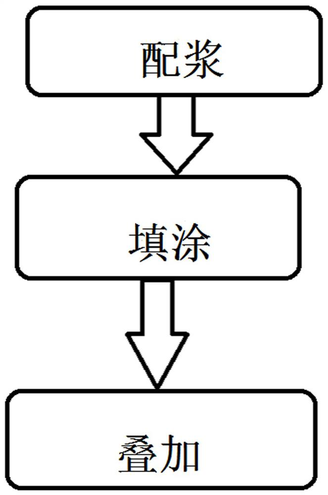
The invention discloses a preparation method of a power battery electrode based on a carbon material, which comprises the following steps: mixing a positive electrode active matter or a negative electrode active matter with an adhesive and a solvent to prepare slurry, filling carbon nanotubes with the slurry, arraying a plurality of carbon nanotubes into a carbon nanolayer, bonding one surface of the carbon nanolayer with foamy carbon, wherein the foamy carbon contains carbon aerogel; the other side of the carbon nanolayer is bonded with a fiber layer formed by cellulose nanofibers, the other side of the fiber layer is bonded with foamy carbon to form a conductive layer, the conductive layer is bonded on a substrate, and zinc ferrite, a carbon material and a nanomaterial are distributed in each conductive layer and are combined, so that the conductivity and the heat resistance of the battery are enhanced, the electric power of the battery is improved, and the service life of the battery is prolonged. The fiber layer formed by the cellulose nanofibers increases the mechanical strength of the battery and prolongs the service life of the battery, and meanwhile, the cellulose has heat insulation property, so that the carbon nanolayer cannot be damaged due to overheating in the charging and using processes of the battery, and the cycle life of the battery is prolonged.

Description

technical field [0001] The invention relates to the field of battery manufacturing, in particular to a method for preparing a power battery electrode based on a carbon material. Background technique [0002] A component in an electronic or electrical device or equipment that is used as two ends of input or output current in a conductive medium (solid, gas, vacuum or electrolyte solution). The pole that inputs current is called the anode or positive pole, and the pole that emits current is called the cathode or negative pole. There are various types of electrodes, such as cathode, anode, welding electrode, electric furnace electrode, etc. In the battery, the electrode generally refers to the position where the redox reaction occurs with the electrolyte solution. There are positive and negative electrodes. Generally, the positive electrode is the cathode, which gains electrons and undergoes a reduction reaction, and the negative electrode is the anode, which loses electrons a...

Claims


Application Information

Patent Timeline
IPC IPC(8): H01M4/04H01M4/587
CPCH01M4/04H01M4/587Y02P70/50
Inventor 张鑫扬
Owner 苏州零号元素新材料科技有限公司
Learn More