
Multi-valued memory

A memory and charge storage technology, applied in semiconductor devices, electro-solid devices, climate sustainability, etc., can solve the problems of complex logic circuits, shortened refresh time, chip surface damage, etc., achieve simple circuit architecture, and improve integration density. , The effect of reducing the circuit design area

Pending Publication Date: 2022-08-05
GALAXYCORE SHANGHAI
View PDF0 Cites 0 Cited by
  • Summary
  • Abstract
  • Description
  • Claims
  • Application Information

AI Technical Summary

Problems solved by technology

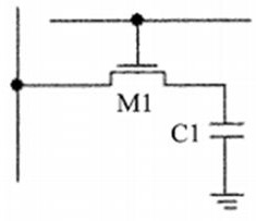
The capacitor C1 of DRAM is generally formed in a stacked or trenched manner. The advantage is that it occupies a small area and can achieve a large capacity. The disadvantage is that the process is much more complicated than the logic circuit, and the access speed is slower than that of SRAM.
Another disadvantage of DRAM is that the memory cells are based on the amount of charge stored on capacitor C1, which decreases with time and temperature and must therefore be refreshed periodically to maintain the correct information they originally remembered
Another disadvantage of DRAM is that due to the conductive interconnection between capacitor C1 and MOS transistor M1, there is a contact hole for conductive interconnection, which needs to be in contact with the silicon surface when interconnecting with the MOS transistor. In this way, there will be an interface state at the contact interface between the contact hole and the silicon, and the electrons in the interface state are relatively active (plasma etching is required when making the contact hole, which will cause damage to the chip surface, and the contact of the two interfaces will be damaged at the same time. There are interface states. Due to the existence of interface states, there are a large number of defect centers on the surface, which makes it easy for carriers to be captured and released on the surface, which greatly increases leakage), and leakage is a problem that is very difficult to control, (increased leakage will lead to refresh Time is shortened, power consumption is increased), and DRAM and SRAM will have reset noise when reading and writing

Method used


Image

  • Multi-valued memory
  • Multi-valued memory
  • Multi-valued memory

Examples


Embodiment Construction

[0043] In the description below, many specific details are explained to fully understand the invention. However, the present invention can be implemented in many other ways that are different from this description. Technical personnel in the art can do similar promotion without violation of the connotation of the invention. Therefore, the invention is not restricted by the specific implementation of the following publicity.

[0044] Secondly, the present invention uses a schematic diagram for detailed description. When detailing the examples of the present invention, in order to facilitate the explanation, the schematic diagram is only an instance, and it should not limit the scope of the protection of the invention.

[0045] In order to make the above invention's above, characteristics, and advantages of the present invention more obvious, the following combined with the attachment of the attachment to describe the method of the present invention in detail.

[0046] The invention...


PUM


Abstract

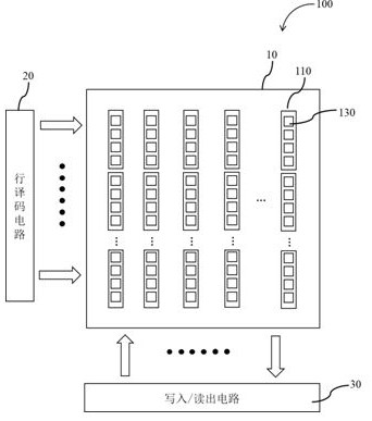
The embodiment of the invention discloses a multi-valued memory. The multi-valued memory comprises a plurality of memory sub-columns; each storage sub-column comprises a floating diffusion region and a plurality of storage units; the storage unit at least comprises a charge storage area and a corresponding transfer transistor; wherein the charge storage region comprises a semiconductor substrate, and the semiconductor substrate is provided with a hole structure; and the doped epitaxial layer is filled in the hole structure and forms a lateral PN junction capacitor with the semiconductor substrate so as to realize a charge storage function. The charge storage area of the storage unit is different from a traditional structure, the holes are formed in the charge storage area through etching, the charge storage area is prepared through epitaxy in the holes, and the structure of the charge storage area improves the full well capacity.

Description

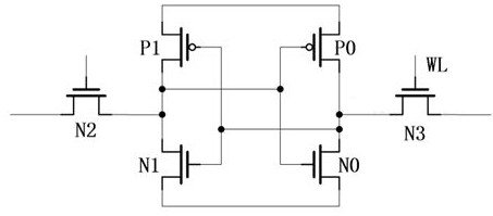
Technical field [0001] The invention involves the field of storage treatment, especially a multi -value memory. Background technique [0002] The storage data of the random access memory (RAM, Random Access Memory) can be read or written on demand, and the speed of reading and writing has nothing to do with the storage location of the data. This memory is the fastest in the memory in memory, but it will be lost when power off, so it is mainly used to store data used for a short time. According to different storage information, random memory can be divided into static random memory (SRAM) and dynamic random memory (DRAM). [0003] The existing SRAM is like figure 1 It is shown that its storage unit is a trigger, consisting of 6 MOS tube, namely the first MOS tube P0, the second MOS tube P1, the third MOS tube N0, the fourth MOS tube N1, the fifth MOS tube N2, the first, the first Six MOS tube N3, which has two stable states, also known as dual -stabilized triggers. SRAM has a fast...

Claims


Application Information

Patent Timeline
IPC IPC(8): H01L27/11521H01L27/11526H01L27/11551H01L27/11568H01L27/11573H01L27/11578
CPCH10B41/40H10B41/20H10B41/30H10B43/40H10B43/20H10B43/30Y02D10/00
Inventor 赵立新杨瑞坤李继刚
Owner GALAXYCORE SHANGHAI
Learn More