Casing and fluid power equipment

A casing and fluid channel technology, applied in mechanical equipment, machines/engines, components of pumping devices for elastic fluids, etc., can solve problems affecting compressor efficiency, momentum exchange loss, etc., and achieve good application prospects. Reduce the loss of efficiency and improve the effect of aerodynamic interference noise

Pending Publication Date: 2022-08-05
BEIHANG UNIV
View PDF8 Cites 0 Cited by
  • Summary
  • Abstract
  • Description
  • Claims
  • Application Information

AI Technical Summary

Problems solved by technology

[0003] The interaction between the strong leakage vortex, shock wave and boundary layer in the blade tip area of ​​the high-load compressor has an important impact on its stability. The casing treatment is a method that can effectively improve the flow in the blade tip area of ​​the compressor and increase the stall margin The passive control method of speed is specifically manifested as: digging grooves, opening slots, or constructing porous inner walls at the corresponding positions on the top of the first-stage or several-stage rotors on the compressor casing to improve the flow in the blade tip area and delay the compression time. Compressor stall suppresses the stall of the airflow in the tip area and reduces the flow loss, but it is often easy to cause momentum exchange loss due to the large return flow in the tip area, which seriously affects the efficiency of the compressor, and is accompanied by an increase in aerodynamic noise

Method used


Image

  • Casing and fluid power equipment
  • Casing and fluid power equipment
  • Casing and fluid power equipment

Examples


Embodiment Construction

[0021] The present disclosure will be further described in detail below in conjunction with the accompanying drawings and embodiments. It should be understood that the specific embodiments described herein are only used to explain the related content, but not to limit the present disclosure. In addition, it should be noted that, for the convenience of description, only the parts related to the present disclosure are shown in the drawings.

[0022] It should be noted that the embodiments of the present disclosure and the features of the embodiments may be combined with each other unless there is conflict. The present disclosure will be described in detail below with reference to the accompanying drawings and in conjunction with the embodiments.

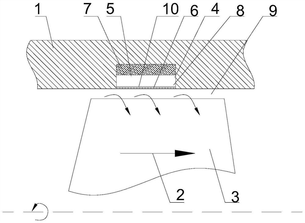
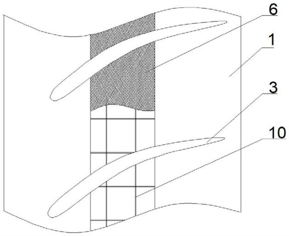
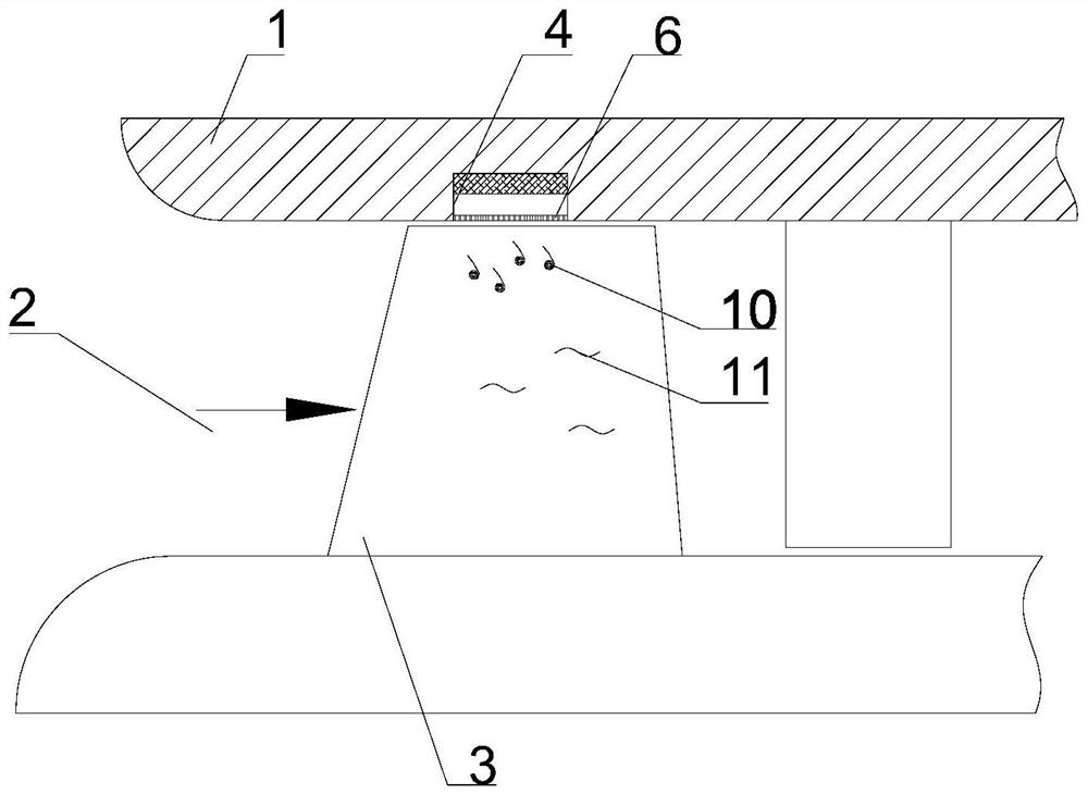
[0023] see image 3 As shown, a fluid power device according to an embodiment of the present disclosure, the fluid power device can be a compressor, an engine, a water pump, an oil pump, etc.; it includes a casing 1, and the casing 1...


PUM


Abstract

The fluid power equipment comprises a casing body, a fluid channel is formed in the casing body, an impeller with blades can be installed in the fluid channel, at least one concave groove is formed in the inner wall face of the casing body, a concave inner cavity is formed in the concave groove, and the concave groove is continuously or intermittently formed in the circumferential direction of the casing body. A net-shaped film with a certain punching rate (20%-50%) is arranged at the opening position of the concave groove. By means of the characteristics that the through holes in the net-shaped film are permeable in pressure and hinder bias flow, on the basis that the stability expansion effect is guaranteed, the net-shaped film serves as the inner wall face of the casing body, radial momentum exchange between main flow in a fluid channel and fluid leakage flow in a pure concave groove is weakened, efficiency loss is reduced, and the stability of the casing is improved. The step structure between the pure sunken groove and the inner wall surface of the casing body is changed, and the pneumatic interference noise of the sunken groove and a rotor is reduced. The cartridge receiver is simple and compact in structure, can meet the requirement for limiting the size of the cartridge receiver in engineering, and has a good application prospect.

Description

technical field [0001] The present disclosure belongs to the technical field of fluid power, and in particular relates to a casing and fluid power equipment. Background technique [0002] Axial flow compressors are widely used in gas turbine installations, blast furnace blasting, air separation, natural gas liquefaction, heavy oil catalysis and other devices to compress air and other gases, especially as one of the key components of aero-engines, which will directly affect the final thrust of the engine. and efficiency. [0003] The interaction between the strong leakage vortex, shock wave and boundary layer in the blade tip area of ​​a high-load compressor has an important impact on its stability. Case treatment is a method that can effectively improve the flow in the compressor blade tip area and increase the compressor stall margin. The passive control method of the degree of control is embodied as follows: at the corresponding position on the top of one or several stage...

Claims


Application Information

Patent Timeline
Patent Type & Authority Applications(China)
IPC IPC(8): F04D29/52F04D29/66F04D19/00
CPCF04D29/522F04D29/663F04D29/664F04D19/00Y02E10/72
Inventor 孙大坤张嘉铭张明薛勇广高星刘睿孙晓峰
Owner BEIHANG UNIV
Why Eureka
Try Eureka