
Micro electro mechanical millimeter wave antenna

A millimeter-wave antenna and micro-electromechanical technology, applied in the field of antennas, can solve the problems of narrow operating frequency band and low radiation efficiency, and achieve the effects of reducing weight, improving radiation efficiency, and improving stability and reliability

Pending Publication Date: 2022-07-26
赛莱克斯微系统科技(北京)有限公司
View PDF0 Cites 0 Cited by
  • Summary
  • Abstract
  • Description
  • Claims
  • Application Information

AI Technical Summary

Problems solved by technology

[0006] The purpose of the present invention is to provide a micro-electromechanical millimeter-wave antenna to solve the technical problems of narrow operating frequency band and low radiation efficiency in the prior art

Method used


Image

  • Micro electro mechanical millimeter wave antenna
  • Micro electro mechanical millimeter wave antenna
  • Micro electro mechanical millimeter wave antenna

Examples


Embodiment Construction

[0041] The technical solutions in the embodiments of the present invention will be clearly and completely described below with reference to the accompanying drawings in the embodiments of the present invention. Obviously, the described embodiments are only a part of the embodiments of the present invention, rather than all the embodiments. Based on the embodiments of the present invention, all other embodiments obtained by those of ordinary skill in the art without creative efforts shall fall within the protection scope of the present invention.

[0042] In the description of the present invention, it should be understood that the terms "center", "upper", "lower", "front", "rear", "left", "right", "vertical", "horizontal", The orientation or positional relationship indicated by "top", "bottom", "inner", "outer", etc. is based on the orientation or positional relationship shown in the drawings, and is only for the convenience of describing the present invention and simplifying t...


PUM


Abstract

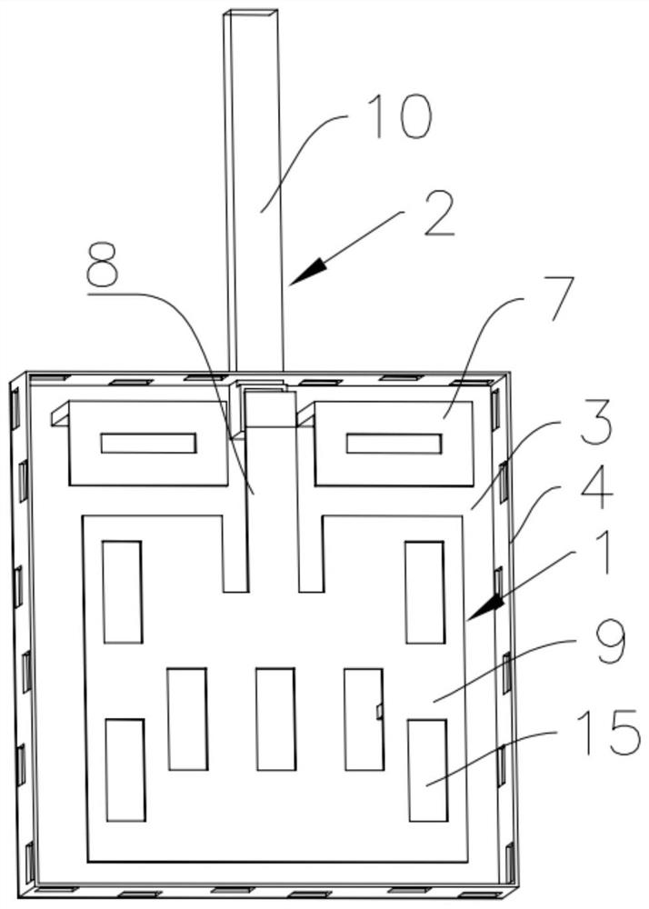
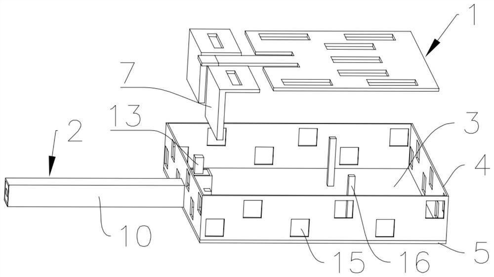
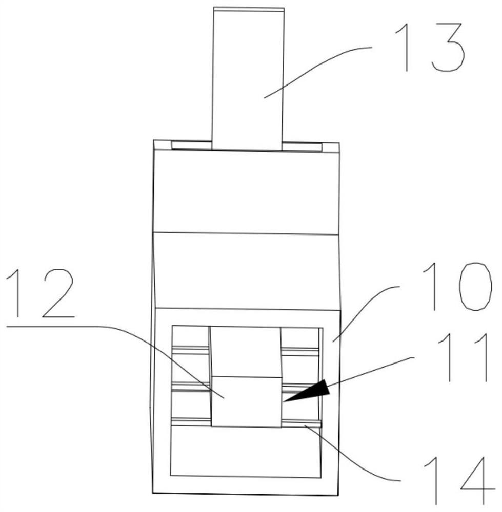
The invention discloses a micro-electro-mechanical millimeter wave antenna, and relates to the technical field of antennae, the micro-electro-mechanical millimeter wave antenna comprises a main radiation unit used for radiating electromagnetic waves and a micro coaxial line used for feeding power to the main radiation unit, and one end of the micro coaxial line is connected with the main radiation unit; the metal groove is used for shielding electromagnetic interference and comprises a side wall and a bottom plate connected with the side wall, a fixing opening is formed in the side wall, the main radiation unit is arranged at a groove opening of the metal groove, the other end of the micro coaxial line extends outwards through the fixing opening, and the outer side wall of the micro coaxial line is connected with the fixing opening; and the parasitic antenna is used for widening the bandwidth of the antenna, one end of the parasitic antenna is connected with the bottom plate, and the other end of the parasitic antenna extends to a notch of the metal groove. The design of the invention can effectively solve the technical problems of narrow working band and low radiation efficiency of a traditional micro-electro-mechanical millimeter wave antenna.

Description

technical field [0001] The present invention relates to the technical field of antennas, in particular to a micro-electromechanical millimeter-wave antenna. Background technique [0002] With the in-depth research and application development of wireless communication and radar, millimeter-wave communication technology has attracted much attention, such as 5G millimeter-wave communication, automotive radar, millimeter-wave satellite communication and other applications. While wireless technology brings convenience to people, it also puts forward higher and higher requirements on performance indicators such as weight, size, and bandwidth of each device in the system. Millimeter waves usually refer to electromagnetic waves with a frequency of 30GHz-300GHz, and their wavelengths are between 1cm-1mm. As one of the most prominent advantages of millimeter wave, the millimeter wave band can achieve wider bandwidth and more channels than the microwave band, and even achieve wireless...

Claims


Application Information

Patent Timeline
Patent Type & Authority Applications(China)
IPC IPC(8): H01Q1/36H01Q1/50H01Q1/52H01Q1/02H01Q5/385
CPCH01Q1/36H01Q1/50H01Q1/526H01Q1/02H01Q5/385
Inventor 刘燕春杨云春陆原裘进梁骥于新元
Owner 赛莱克斯微系统科技(北京)有限公司
Learn More