


Quick Research
Generate reliable direction feasibility study reports for your R&D in just a few steps.

Technical Q&A
Discover and master advanced knowledge NOW. Basics, ideas, possibilities, all at once.

Find Solutions
As an expert in R&D theories, this can generate solutions to your technical problems instantly.

Evaluate Feasibility
Analyze your overall solution with one click, know your potential R&D risks in advance.

Monitor Landscape
Get weekly tech updates, stay abreast of the latest tech innovations and key insights.
Repair system for strengthening oxidation-reduction reaction through in-situ hydraulic driving
A hydraulic drive and restoration system technology, applied in the field of soil restoration, can solve the problems of large amount of treatment process and poor restoration effect of water and soil integration, and achieve good treatment effect, efficient integrated restoration, and low economic cost
- Summary
- Abstract
- Description
- Claims
- Application Information
AI Technical Summary
Problems solved by technology
Method used
Image

Examples
Embodiment 1
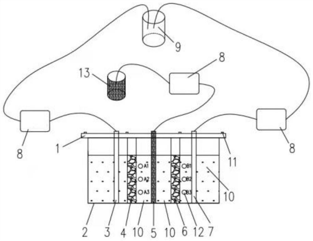
[0041] like figure 1 For ease of understanding, the experimental area of the series reaction grid system is regarded as a seepage box 2 in a square area. A transparent cover 1 is set on the top of the seepage box 2 and is tightened with bolts 11 to prevent the inside of the seepage box 2 from being polluted by the environment. ; The upper surface of the box cover 1 is provided with a first injection port, a second injection port and a third injection port, which correspond to the positions of the first injection well 3, the second injection well 5 and the extraction well 7.
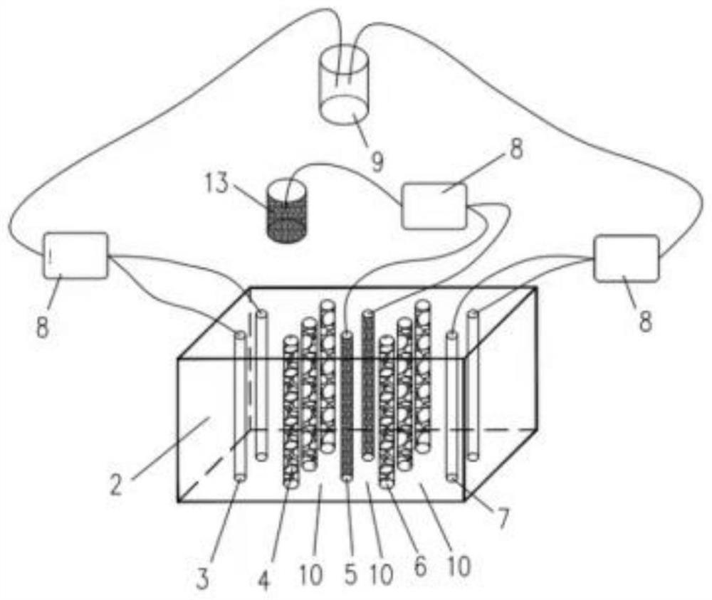
[0042] Further, the present invention includes a seepage tank 2 filled with polluted soil, a hydraulically driven circulation system for promoting the migration of pollutants in the soil, and a series reaction grid system composed of permeable reaction columns. The hydraulic drive circulation system includes a first injection well 3 , an extraction well 7 , a peristaltic pump 8 and a liquid storage tank...
Embodiment 2
[0053] Remediation of soil and simulated groundwater contaminated with naphthalenesulfonic acid, 1,5-naphthalenedisulfonic acid, and 1,3,6-naphthalenetrisulfonic acid under laboratory conditions. A plexiglass container with a length, width and height of 300:150:150 (mm) was filled with 1:1 clay and quartz sand to simulate the soil layer and groundwater with benzenesulfonic acid pollutants dissolved below the surface. The soil reduction and purification unit 4 and the soil oxidation and purification unit 6 are perforated plexiglass tubes pre-buried in the soil layer and filled with biochar-loaded nano-zero valent iron. The pump 8 and the liquid storage tank 9 are connected, and the persulfate injection well 5 is connected with the oxidation tank and the peristaltic pump 8 . The seepage box cover 1 seals the experimental container through bolts, and a sampling port for simulating groundwater is reserved on the side of the experimental container.
[0054] The specific repair ste...
PUM
| Property | Measurement | Unit |
|---|---|---|
| Diameter | aaaaa | aaaaa |
Abstract
Description
Claims
Application Information
 - R&D Engineer
- R&D Manager
- IP Professional
- Industry Leading Data Capabilities
- Powerful AI technology
- Patent DNA Extraction
Browse by: Latest US Patents, China's latest patents, Technical Efficacy Thesaurus, Application Domain, Technology Topic, Popular Technical Reports.
© 2024 PatSnap. All rights reserved.Legal|Privacy policy|Modern Slavery Act Transparency Statement|Sitemap|About US| Contact US: help@patsnap.com