
Electroslag furnace crystallizer structure

A technology of crystallizer and electroslag furnace, applied in the field of crystallizer structure of electroslag furnace, can solve the problems of increased production workload, large loss cost of steel plates, increased consumption of raw materials, etc. The effect of applying the effect

Pending Publication Date: 2022-07-15
湖北正达机械制造有限公司
View PDF0 Cites 0 Cited by
  • Summary
  • Abstract
  • Description
  • Claims
  • Application Information

AI Technical Summary

Problems solved by technology

[0002] In the process of using an electroslag furnace to smelt steel ingots, a steel plate for protecting the ingot will be installed on the basis of the copper plate at the bottom junction. The arc starting point is set on the steel plate for protecting the ingot to achieve the purpose of striking the arc while protecting the bottom junction. This steel plate The middle part will eventually form a part of the steel ingot together with the consumable electrode. During the smelting process of the traditional electroslag furnace, in order to better strike the arc and protect the bottom junction copper plate at the same time, to prevent the molten steel from running out and causing waste and safety accidents, this piece The steel plate is usually made relatively large, so as not to burn out the bottom-junction copper plate, but this method consumes a large steel plate for each furnace of steel ingot smelted, and the loss cost of the steel plate is very large, which also greatly increases the cost of the enterprise. The production cost is high, and after the steel ingot comes out, it is necessary to cut the edge of the steel plate at the bottom of the steel ingot, which greatly increases the production workload and further increases the consumption of raw materials.

Method used


Image

  • Electroslag furnace crystallizer structure
  • Electroslag furnace crystallizer structure
  • Electroslag furnace crystallizer structure

Examples


Embodiment Construction

[0019] The technical solutions of the present invention will be clearly and completely described below with reference to the accompanying drawings. Obviously, the described embodiments are only a part of the embodiments of the present invention, rather than all the embodiments. Based on the embodiments of the present invention, all other embodiments obtained by those of ordinary skill in the art without creative work fall within the protection scope of the present invention.

[0020] In the description of the present invention, it should be noted that the terms "upper", "lower", "inner", "outer" and the like indicate the orientation or positional relationship based on the orientation or positional relationship shown in the drawings, or the invention The orientation or positional relationship that the product is usually placed in use is only for the convenience of describing the present invention or simplifying the description, rather than indicating or implying that the device ...


PUM


Abstract

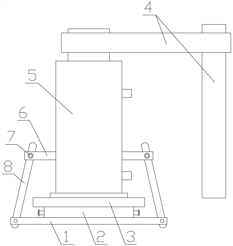
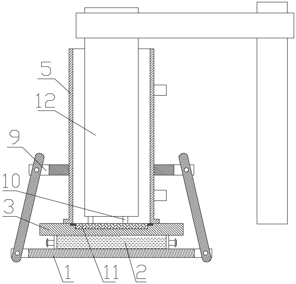
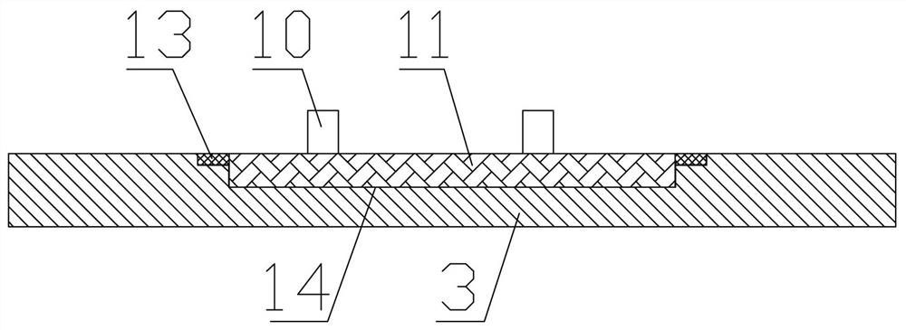
The invention relates to an electroslag furnace crystallizer structure which comprises a bottom crystallizer and an upper crystallizer, a base is arranged at the bottom of the bottom crystallizer, a current-conducting plate is arranged on the bottom crystallizer, the diameter of the current-conducting plate is larger than the outer diameter of a barrel of the upper crystallizer, and a sunken concave table is arranged in the middle of the current-conducting plate and used for positioning. The diameter of the concave table is smaller than the inner diameter of the upper crystallizer barrel, an ingot protection steel plate is placed in the concave table, at least two lug plates are arranged on the peripheral edge of the ingot protection steel plate, a lug plate groove is further formed in the current-conducting plate and corresponds to each lug plate, and the upper end face of each lug plate is flush with the upper end face of the current-conducting plate. The lug plates are flatly pressed on the lower end surface of the upper crystallizer cylinder; n dummy ingot blocks are also arranged on the ingot protection steel plate; the crystallizer structure is an improved design aiming at a traditional electroslag furnace crystallizer, is simple, but has a very prominent using effect, greatly saves materials, reduces energy consumption, and is difficult to think by a conventional technology.

Description

technical field [0001] The invention relates to the technical field of electroslag furnace equipment, in particular to a crystallizer structure of an electroslag furnace. Background technique [0002] In the process of using electroslag furnace to smelt ingots, an ingot guard steel plate will be set on the basis of the bottom junction copper plate, and the arc starting point is set on the ingot guard steel plate to achieve the purpose of arc striking and protect the bottom junction. The middle part will eventually form a part of the steel ingot together with the consumable electrode. In the smelting process of the traditional electroslag furnace, in order to better strike the arc and protect the bottom junction copper plate, prevent the molten steel from running out and cause waste and safety accidents. The steel plate is usually made relatively large, so as not to burn out the bottom-bonded copper plate, but this method consumes a large steel plate for each ingot smelting, ...

Claims


Application Information

Patent Timeline
IPC IPC(8): C22B9/193
CPCC22B9/18
Inventor 吴熹熊卫毫刘合国俞国
Owner 湖北正达机械制造有限公司
Learn More