
Output stage circuit, control method, drive unit and display device

A technology of an output stage circuit and a control method, which is applied in the field of output stage circuits, drive devices, display devices, and control methods, and can solve problems such as increased power supply voltage drop, over-design, and increased peak current, and achieves power supply voltage. The effects of small drop, high circuit stability, and improved drive capability

Pending Publication Date: 2018-12-18
CHIPONE TECH BEIJINGCO LTD
View PDF9 Cites 1 Cited by
  • Summary
  • Abstract
  • Description
  • Claims
  • Application Information

AI Technical Summary

Problems solved by technology

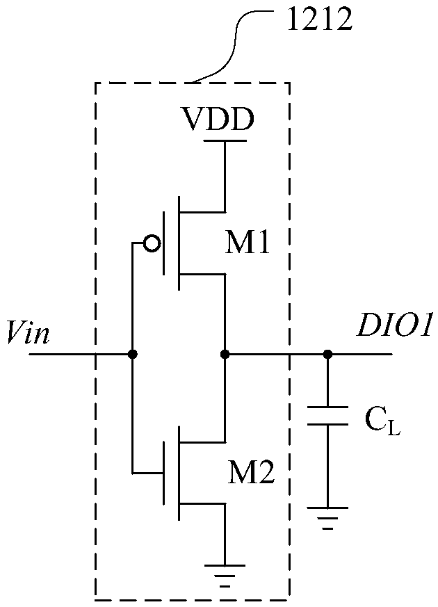
[0005] The output stage circuit of the output buffer of the prior art has the following problems: the output stage circuit of the prior art uses a single transistor to charge the load capacitance to obtain a synchronous signal. Since the application conditions of the chip are unknown, the size of the load capacitance and the working The frequency is unknown, so there will be over-design in the circuit design
For example, in order to improve the driving capability of the circuit, it is necessary to increase the area of ​​the transistor, which will increase the peak current generated instantaneously during the operation of the transistor, and will cause the voltage drop of the power supply to increase when the circuit is in operation. Excessive voltage drop of the power supply will cause The operating voltage of the source driver chip is insufficient, which affects the working performance of the source driver chip

Method used


Image

  • Output stage circuit, control method, drive unit and display device
  • Output stage circuit, control method, drive unit and display device
  • Output stage circuit, control method, drive unit and display device

Examples


Embodiment Construction

[0039] Hereinafter, the present invention will be described in more detail with reference to the accompanying drawings. In the various figures, identical elements are indicated with similar reference numerals. For the sake of clarity, various parts in the drawings have not been drawn to scale. Also, some well-known parts may not be shown.

[0040] In the following, many specific details of the present invention are described, such as device structures, materials, dimensions, processing techniques and techniques, for a clearer understanding of the present invention. However, the invention may be practiced without these specific details, as will be understood by those skilled in the art.

[0041] The invention can be embodied in various forms, some examples of which are described below.

[0042] Figure 4 An equivalent circuit diagram of the liquid crystal display device according to the first embodiment of the present invention is shown.

[0043] The liquid crystal display...


PUM


Abstract

The embodiment of the invention discloses an output stage circuit featured by comprising a first input module and a second input module connected in parallel between a power voltage and the ground; the first input module is used for providing a first charge / discharge path of a load capacitor according to an input signal; the second input module is used for providing a second charge / discharge pathof the load capacitor according to a control signal; the first and second input modules are used for charging / discharging the load capacitor so as to obtain an output signal, thus improving the circuit driving ability, and reducing transistor dimensions in the input module. The embodiment also discloses an output stage circuit control method, a drive unit and a display device.

Description

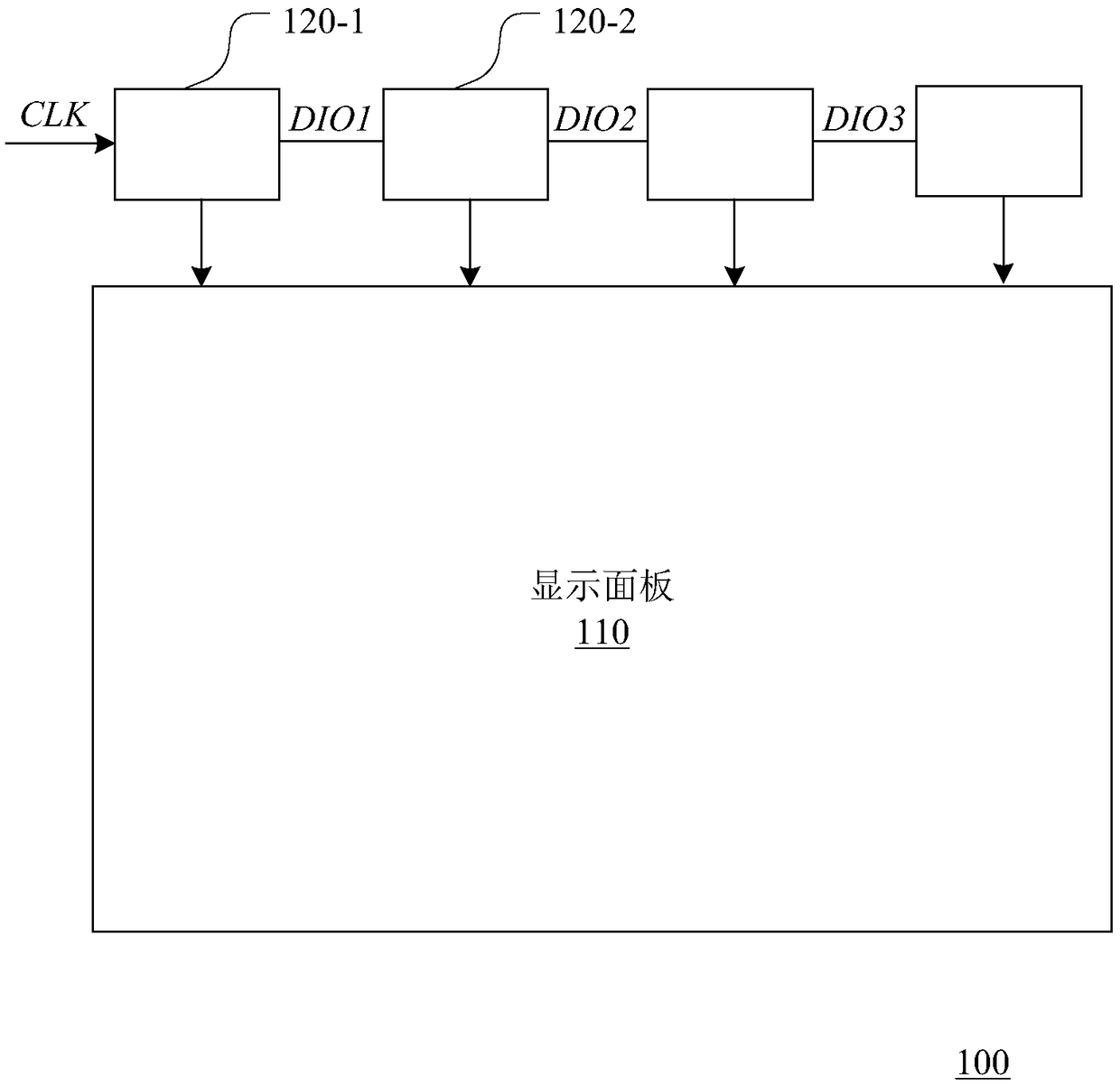
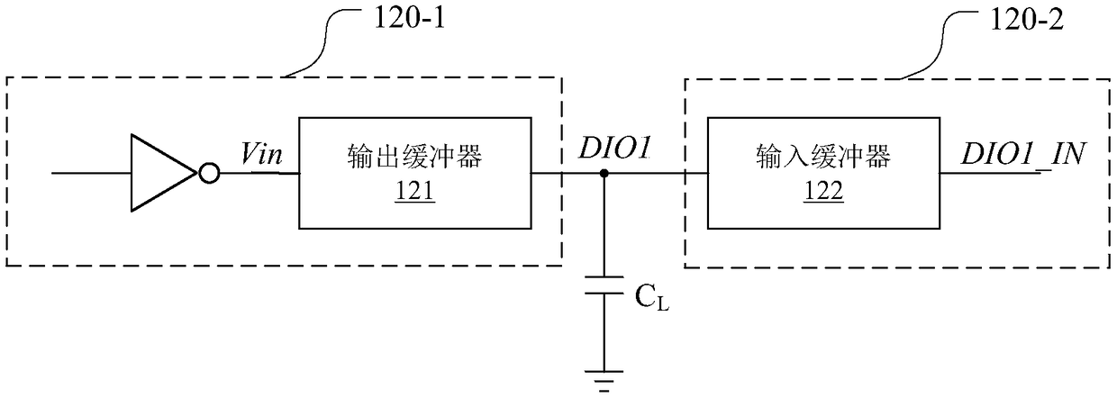
technical field [0001] The present application relates to the field of electronic circuits, and more specifically, to an output stage circuit, a control method, a driving device, and a display device. Background technique [0002] Output buffers are often used in various electronic devices to isolate signal input terminals and output terminals, so as to prevent the signal input terminals from being affected by loads and enhance the ability of signals to drive loads. Such as figure 1 As shown, the existing liquid crystal display device includes a plurality of cascaded source driver chips. The multiple source driver chips perform data synchronization through the synchronization signal DIO. For example, after the source driver chip 120-1 receives data, it provides the source driver chip 120-2 with the synchronization signal DIO1, and the source driver chip 120-2 starts to receive data according to the synchronization signal DIO1, and so on. After all the source driver chips ...

Claims


Application Information

Patent Timeline
Patent Type & Authority Applications(China)
IPC IPC(8): G09G3/36
CPCG09G3/3677G09G3/3688
Inventor 黄蕊林家弘
Owner CHIPONE TECH BEIJINGCO LTD
Learn More