
Grinding equipment

A technology of equipment and grinding discs, which is applied in the direction of grinding/polishing equipment, metal processing equipment, electrical components, etc., to achieve the effect of improving grinding yield, improving overall productivity, and reducing consumption area

Active Publication Date: 2014-08-13
VANGUARD INTERNATIONAL SEMICONDUCTOR CORPORATION
View PDF4 Cites 0 Cited by
  • Summary
  • Abstract
  • Description
  • Claims
  • Application Information

AI Technical Summary

Problems solved by technology

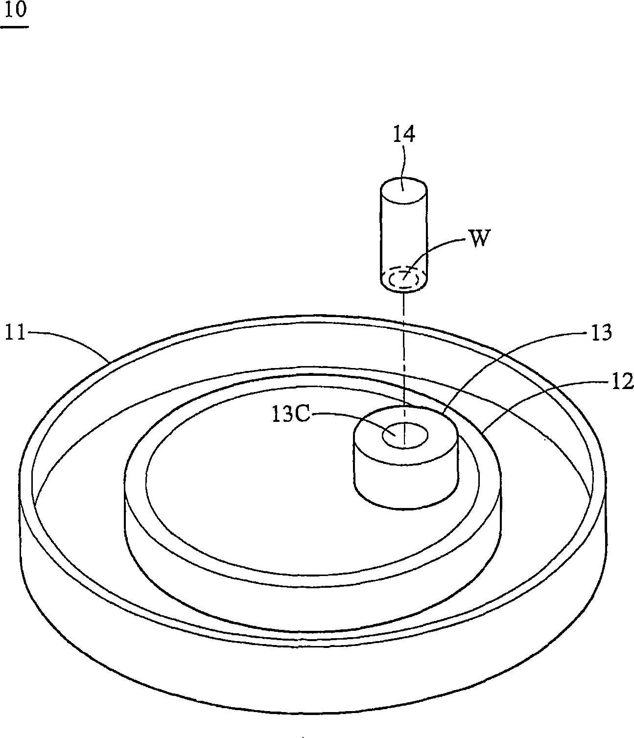
[0004] However, when grinding, the operator must fix the position of the axis 14 by hand, the success rate of grinding is low, and the quality is not stable; Due to the limitation of the number of grinding equipment, each grinding equipment 10 only allows two people to work at the same time, and one person can only grind a group of wafers W, which consumes a lot of grinding time; in addition, the above grinding method must use the help of the collar 13, so When grinding the wafer W, the collar 13 is worn, and the contact area between the grinding table 12 and the collar 13 is also consumed at the same time, resulting in waste of resources

Method used


Image

  • Grinding equipment
  • Grinding equipment
  • Grinding equipment

Examples


Embodiment Construction

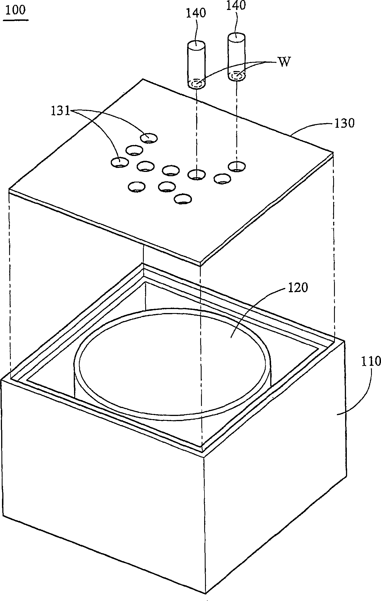
[0027] It should be noted that in this embodiment, the auxiliary jig 130 is mounted on the edge of the opening of the main body 110 , but it is not limited thereto, as long as the auxiliary jig 130 can be fixed above the grinding disc 120 .

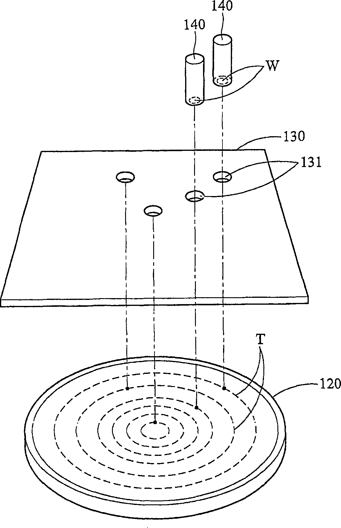
[0028] When grinding the wafer W, the operator puts the end face of the shaft 140 down into one of the holes 131 so that the end face of the shaft 140 is opposite to the grinding disc 120, and the wafer W is brought into contact with the rotating grinding disc 120 to Wafer W is ground.

[0029] Cooperate see image 3 , the grinding disc 120 has a plurality of tracks T, and the position of each hole 131 is set relative to each non-repeating track T, so that each wafer W can be ground on a different track T. Also because of this, there is no limit on the number of the axis 140 and the hole 131 , it only needs to be determined that each wafer W can be ground on different tracks T.

[0030] The diameter of the hole 131 is slightly larger th...


PUM


Abstract

The invention provides a grinding device, which is used to grind at least one wafer, and includes a main body, a grinding disc, an auxiliary jig and at least one axis, and the grinding disc is rotatably arranged on the main body; the auxiliary jig The tool is arranged above the grinding disc, and has at least one positioning part, and the positioning part is a hole; the axis has an end surface, and the wafer is fixed on the end surface; when the axis is placed in the positioning part, the positioning part fixes the axis position so that the end face is opposite to the grinding disc. The grinding equipment of the present invention can simultaneously grind multiple groups of wafer test pieces to improve the overall productivity; and can adopt a fully automated grinding method to improve the problem of uneven manual force application and improve the grinding yield; and can reduce the consumption of grinding discs area, while saving material costs.

Description

technical field [0001] The invention relates to a grinding device, in particular to a grinding device capable of grinding multiple wafers at the same time. Background technique [0002] see figure 1 , figure 1 It is a schematic diagram of an existing grinding equipment 10 . When grinding or polishing a wafer W in the existing grinding equipment, the wafer is usually manually placed on the grinding equipment 10 for grinding. The grinding device 10 includes a main body 11 , a grinding table 12 and a collar 13 . When the polishing table 12 is used to rotate on the main body 11 , the wafer W is rubbed against the polishing table 12 to be polished. [0003] The wafer W is pre-fixed on an axis 14, and then the axis 14 is placed in the center hole 13C of the collar 13, so that the wafer W can contact the grinding table 12 through the center hole 13C, and the assistance of the collar 13 can help maintain The uniformity of the contact surface between the wafer W and the polish...

Claims


Application Information

Patent Timeline
Patent Type & Authority Patents(China)
IPC IPC(8): B24B29/00H01L21/304
Inventor 邱瑞春
Owner VANGUARD INTERNATIONAL SEMICONDUCTOR CORPORATION
Learn More