Roadbed dynamic displacement determination method based on dynamic stress and vibration displacement time history signals

A vibration displacement and determination method technology, which is applied to roads, roads, instruments, etc., can solve the problems of increasing test errors at fixed points, increasing test errors, and insufficient rigidity, so as to improve test efficiency, avoid test errors, and reduce The effect of testing costs

Active Publication Date: 2022-07-08
SOUTHWEST JIAOTONG UNIV
View PDF4 Cites 0 Cited by
  • Summary
  • Abstract
  • Description
  • Claims
  • Application Information

AI Technical Summary

Problems solved by technology

The existing methods mainly use sensors such as LVDT and eddy current, and clamp the sensor on the rigid support drawn from the fixed point. The fixed point and the measuring point are both located on the subgrade structure due to environmental restrictions, and there are the following problems: ① Use a small Large rigidity bracket, the position of the fixed point is close to the measuring point, and the background response of the fixed point will inevitably increase the test error; ②Increasing the distance between the fixed point and the measuring point to ensure the rigidity of the bracket will inevitably lead to an increase in size, which will greatly increase the test cost , may also affect the safe operation of high-speed trains, while limiting the size of the bracket may not be rigid enough, and the deformation of the bracket structure caused by the train load will also increase the test error

Method used


Image

  • Roadbed dynamic displacement determination method based on dynamic stress and vibration displacement time history signals
  • Roadbed dynamic displacement determination method based on dynamic stress and vibration displacement time history signals
  • Roadbed dynamic displacement determination method based on dynamic stress and vibration displacement time history signals

Examples


Embodiment Construction

[0029] The embodiments of the present invention will be further described below with reference to the accompanying drawings.

[0030] Before describing the specific embodiments of the present invention, in order to make the solution of the present invention clearer and more complete, the definitions of abbreviations and key terms that appear in the present invention are first described:

[0031] B-spline curve fitting: It is mainly an LSQ fitting problem, and the main idea is also the idea of ​​the least squares method.

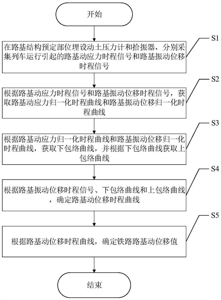
[0032] like figure 1 As shown, the present invention provides a method for determining dynamic displacement of roadbed based on dynamic stress and vibration displacement time-history signal, comprising the following steps:

[0033] S1: Bury earth pressure gauges and vibration pickups at predetermined positions of the subgrade structure, and collect the subgrade dynamic stress time-history signal and subgrade vibration displacement time-history signal caused ...


PUM


Abstract

The invention discloses a roadbed dynamic displacement determination method based on dynamic stress and vibration displacement time history signals. The roadbed dynamic displacement determination method comprises the following steps that S1, roadbed dynamic stress time history signals and roadbed vibration displacement time history signals caused by train operation are collected; s2, obtaining a roadbed dynamic stress normalization time history curve and a roadbed vibration displacement normalization time history curve; s3, acquiring a lower envelope curve and an upper envelope curve; s4, determining a roadbed dynamic displacement time history curve; and S5, determining a railway roadbed dynamic displacement value. According to the method, on the basis of an actually measured roadbed dynamic stress time-history curve and a roadbed vibration displacement time-history curve, a roadbed dynamic displacement time-history curve is obtained through correction by using a signal processing technology, a sensor used for testing is directly placed at a measuring point part, and additional fixed points and rigid supports do not need to be selected; the contradiction between the position of a fixed point and the size of the rigid bracket caused by the limitation of the environment in the existing test method is overcome.

Description

technical field [0001] The invention belongs to the technical field of roads and railways, and in particular relates to a method for determining dynamic displacement of roadbed based on dynamic stress and vibration displacement time-history signals. Background technique [0002] Train operation imposes moving axle loads on the line structure, and at the same time generates dynamic excitations caused by track irregularities and wheel out-of-roundness. The line structure directly bears the train load, and its service performance is related to the safety of high-speed rail operations. As a main type of off-line structure, the subgrade needs to fully consider the impact of train dynamic loads in the process of design, construction and operation and maintenance. The dynamic response test results. The subgrade is a geostructure filled with granular materials, and the dynamic test should not only reflect the response of the surface of the structure, but also pay attention to the ...

Claims


Application Information

Patent Timeline
Patent Type & Authority Applications(China)
IPC IPC(8): G06F17/10G01N3/00G01N3/02E01C3/00E01B2/00
CPCG06F17/10G01N3/00G01N3/02E01C3/00E01B2/006Y02T90/00
Inventor 罗强冯桂帅王腾飞张良蒋良潍刘宏扬谢宏伟付航周建详叶庆志
Owner SOUTHWEST JIAOTONG UNIV
Why Eureka
Try Eureka