Far-end true time delay beamforming implementation method based on few-mode fiber

A few-mode fiber, beamforming technology, applied in the field of microwave photonics, to achieve the effect of reducing demand, reducing cost, phase and delay jitter elimination

Pending Publication Date: 2022-06-07
PEKING UNIV
View PDF6 Cites 0 Cited by
  • Summary
  • Abstract
  • Description
  • Claims
  • Application Information

AI Technical Summary

Problems solved by technology

[0005] In order to overcome the time delay jitter caused by inter-mode interference, the present invention provides a solution using an ASE light source as an optical carrier

Method used


Image

  • Far-end true time delay beamforming implementation method based on few-mode fiber
  • Far-end true time delay beamforming implementation method based on few-mode fiber
  • Far-end true time delay beamforming implementation method based on few-mode fiber

Examples


Embodiment Construction

[0024] The solution of the present invention will be described in further detail below with reference to the accompanying drawings.

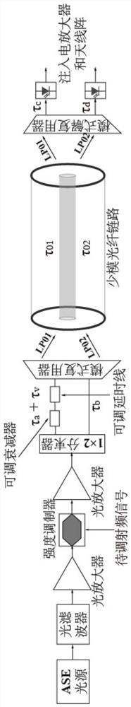
[0025] The scheme principle of the present invention is as follows figure 1 shown. The implementation here is exemplified by a two-element beamforming system using LP01 and LP02 modes of transmission. At the central office, the ASE light source is narrow-band filtered with an optical filter. The narrow-band filtered ASE light source is amplified by an optical amplifier and injected into the intensity modulator. The radio frequency signal to be modulated is modulated on the ASE optical carrier, amplified again by the optical amplifier, and split into a first delay copy signal and a second delay copy signal by a 1*2 coupler. After the first time-delayed copy signal passes through the adjustable optical attenuator and the adjustable optical delay line, the mode multiplexer is used to inject the LP01 mode of the few-mode fiber and transmit to the...


PUM


Abstract

The invention discloses a far-end true time delay beamforming implementation method based on a few-mode fiber, and the method comprises the steps: 1), adjusting the bandwidth of an ASE light source according to the signal-to-noise ratio of a to-be-transmitted radio frequency signal, and taking the adjusted ASE light source as an optical carrier; 2) modulating the optical carrier through the radio frequency signal to be transmitted to obtain an optical carrier radio frequency signal, dividing the optical carrier radio frequency signal into N paths of time delay copy signals, and injecting the N paths of time delay copy signals into a few-mode optical fiber link through a mode multiplexer in a corresponding mode and transmitting the N paths of time delay copy signals to a far-end mode demultiplexer; (3) a mode demultiplexer carries out demultiplexing on the N paths of time delay copy signals and couples the N paths of time delay copy signals to N paths of single-mode tail fibers; wherein the demultiplexed ith-path time delay copy signal is input into the ith-path single-mode tail fiber, and the length of the ith-path single-mode tail fiber meets the condition that the time delay difference between the ith-path time delay copy signal and the inter-mode crosstalk is far greater than the coherence time of the ASE light source; and 4) converting and amplifying the N paths of single-mode tail fiber output signals, and injecting the signals into N units of the antenna array for emission.

Description

technical field [0001] The invention relates to the field of microwave photonics, in particular to a method of amplifying a spontaneous emission light source (hereinafter referred to as an ASE light source) as an optical carrier, eliminating the coherence between a signal and inter-mode crosstalk, and avoiding the influence of inter-mode interference on time delay jitter, Thus, a remote true-delay beamforming method based on few-mode fiber is realized. Background technique [0002] Beamforming is a key technology in 5G mobile communications, which can effectively reduce electromagnetic interference in wireless links and greatly improve radiation gain in specific directions. The beamformer realized by optical true delay can avoid the problem of beam squint, thus supporting the access of broadband radio frequency signals. Due to this advantage, a large number of local beamforming schemes have been proposed in recent years. However, in the 5G mobile communication system, the ...

Claims


Application Information

Patent Timeline
Patent Type & Authority Applications(China)
IPC IPC(8): H04B10/2507H04B10/61
CPCH04B10/2507H04B10/616Y02D30/70
Inventor 张宸博何必博刘容玮雷鹏李彦锟陈章渊解晓鹏胡薇薇
Owner PEKING UNIV
Why Eureka
Try Eureka