
High-precision measurement system for DS/FH spread spectrum signal carrier frequency

A technology of measuring system and carrier frequency, applied in modulation carrier system, transmission system, carrier adjustment and other directions, can solve the problems of not measuring the carrier Doppler rate of change, complicated equipment, poor frequency measurement accuracy, etc., to shorten the data processing time , The effect of reducing the amount of related calculations and improving the measurement accuracy

Active Publication Date: 2022-05-27
10TH RES INST OF CETC
View PDF7 Cites 1 Cited by
  • Summary
  • Abstract
  • Description
  • Claims
  • Application Information

AI Technical Summary

Problems solved by technology

DS spread spectrum has the advantages of good communication concealment and anti-multipath interference performance, but its processing gain is limited, the synchronization requirements are strict, and the far-near effect is not good. FH spread spectrum has good far-near characteristics and can achieve very wide communication The advantages of wide bandwidth and avoiding single-frequency interference, but the equipment is complex in fast hopping, and the concealment is poor in slow hopping. DS / FH spread spectrum technology increases the working method of frequency hopping on the basis of DS spread spectrum, which combines DS spread spectrum and FH The advantages of spread spectrum include the good concealment of DS spread spectrum and the avoidance of interference by FH spread spectrum. It also overcomes the near-far effect of DS spread spectrum system and breaks through the bottleneck of a single spread spectrum method. Therefore, DS / FH spread spectrum technology not only occupies an important position in the military field, but also has great significance in the field of civilian communications
[0004] In complex environments such as high dynamics, low signal-to-noise ratio, and strong interference, the bandwidth of the high-precision signal tracking loop is extremely narrow. To achieve reliable tracking of spread spectrum communication, the carrier frequency of the received signal must be determined on the basis of prior signal capture. Carry out further accurate measurement. The purpose of accurate measurement of the carrier frequency is to make the difference between the carrier frequency of the local signal and the carrier frequency of the received signal smaller, so that the carrier loop can perform frequency synchronization quickly and reliably. If the difference between the local signal and the received signal If the error exceeds the traction range of the tracking loop, the tracking loop will usually fail to lock normally
[0005] Traditional measurement methods generally use Fast Fourier Transform (FFT) to directly measure the frequency of the sampled data of the received signal. The influence of Doppler, and only the rough measurement of carrier Doppler frequency shift is realized, the rate of change of carrier Doppler is not measured, and the frequency offset caused by high-speed maneuvering of the target, processing time delay, etc. cannot be corrected, and the frequency measurement accuracy is poor , unable to meet the performance requirements of the actual receiving system, therefore, how to accurately, quickly and effectively measure the carrier frequency of DS / FH spread spectrum signals has become a key core technology to be solved urgently in the DS / FH spread spectrum communication system

Method used


Image

  • High-precision measurement system for DS/FH spread spectrum signal carrier frequency
  • High-precision measurement system for DS/FH spread spectrum signal carrier frequency
  • High-precision measurement system for DS/FH spread spectrum signal carrier frequency

Examples


Embodiment

[0055] Taking the DS / FH spread spectrum signal transmitted by a satellite as an example, the operating frequency f RF is 22.0GHz, the direct spread code rate R ds R ds is 10.0Mcps, the direct spreading code period L ds is 2500, the frequency hopping rate R fh 20kHop / s, frequency hopping interval f fh for 40kHz modulation information rate R b is 4.0kbps, the carrier Doppler frequency shift range is ±900.0kHz, and the carrier Doppler rate of change range is ±7.5kHz / s.

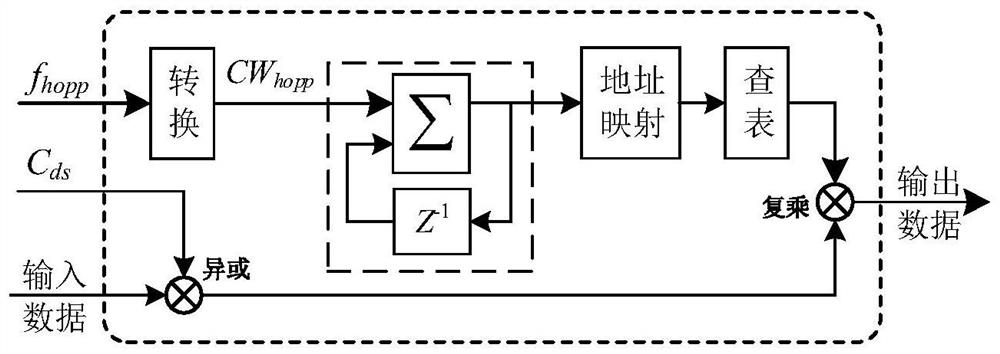
[0056] The spread hopping pattern module is based on the direct spread code phase, the frequency hopping code phase and the carrier Doppler frequency shift f in the captured information acq , generate the direct-spread pseudocode C in real time ds and the hopping frequency f hopp .

[0057] The despreading and dehopping module is based on the real-time direct-spreading pseudocode C ds and the hopping frequency f hopp Pseudo-code despreading and frequency de-hopping are performed on the received signal. ...


PUM


Abstract

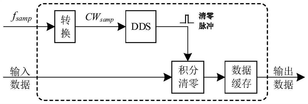
The invention discloses a high-precision measurement system for a DS / FH spread spectrum signal carrier frequency. The measurement system comprises a spreading and hopping pattern module, a de-spreading and de-hopping module, a sampling cache module, a two-dimensional slotting module, a compensation correction module, an integral accumulation module, a peak value search module and a frequency resolving module. The de-spreading and de-hopping module carries out pseudo code de-spreading and frequency de-hopping on the received signal according to the real-time direct spread pseudo code and the frequency hopping frequency; the two-dimensional slotting module divides the movement speed and the acceleration into a plurality of two-dimensional search sub-slots according to the carrier Doppler frequency shift and the carrier Doppler change rate range in the captured information; the compensation and correction module is used for carrying out carrier frequency compensation and correction on the sampling data read by the sampling cache module in an inverted sequence according to the hopping frequency output by the spread hopping pattern module and the sub-slot information output by the two-dimensional slotting module; and the frequency resolving module is used for resolving the carrier Doppler frequency shift and the carrier Doppler change rate of the received signal at the output moment by adopting a time correction technology according to the integral peak value sub-slot information.

Description

technical field [0001] The invention belongs to the field of wireless communication, and relates to a high-precision measurement system for DS / FH spread spectrum signal carrier frequency. Background technique [0002] Spread spectrum communication technology has been widely used in military and civil communication systems due to its advantages of good confidentiality, strong anti-interference ability and high spectral efficiency. Spread spectrum communication uses spread spectrum code at the transmitting end to modulate baseband information, and then receive it. The terminal uses the same spreading code for despreading to recover the original baseband information. The frequency bandwidth occupied by the signal during the transmission process is much larger than the bandwidth required for transmitting the information, which has become the mainstream technology of radio communication. [0003] Spread spectrum communication can be divided into direct sequence (DS) spread spectr...

Claims


Application Information

Patent Timeline
Patent Type & Authority Applications(China)
IPC IPC(8): H04B1/7075H04B1/7156H04L27/00
CPCH04B1/7075H04B1/7156H04L27/0014H04B2001/71563Y02D30/70
Inventor 金磊古礼衍王媛曾富华袁田王娜
Owner 10TH RES INST OF CETC
Learn More