Eureka AIR delivers breakthrough ideas for toughest innovation challenges, trusted by R&D personnel around the world.

Centralized photovoltaic power station with stable output voltage

A technology for output voltage and photovoltaic power stations, applied in photovoltaic power stations, photovoltaic power generation, photovoltaic modules, etc., can solve the problems of unstable voltage output, inconvenient disassembly and assembly, and failure to take into account, so as to achieve the goal of increasing power generation and improving stability Effect

Pending Publication Date: 2022-05-27
江苏富士特电气技术有限公司
View PDF17 Cites 2 Cited by
  • Summary
  • Abstract
  • Description
  • Claims
  • Application Information

AI Technical Summary

Problems solved by technology

The utility model effectively cleans the photovoltaic power station, ensures the use effect, reduces labor consumption and maintenance costs, and further meets the use requirements. However, the photovoltaic power station in the above-mentioned public documents mainly considers how to clean the photovoltaic power station conveniently and quickly. It does not take into account that the existing photovoltaic power plants are extremely vulnerable to external factors, resulting in unstable voltage output;
[0005] 2. The patent document CN213661513U discloses a ground centralized photovoltaic power station component support steel pipe pile, including a bottom pipe pile. The internal activities of the bottom pipe pile are provided with a connecting column, and the lower part of the connecting column is equidistantly fixedly connected with A plurality of anti-drawing components, the outer wall of the bottom pipe pile is equidistantly provided with a plurality of hook outlets on opposite sides, and the hook outlets correspond to the anti-pullout components, and the upper part of the bottom pipe pile is slidingly connected with Adjusting the pipe, by setting the anti-pullout component, the anti-pullout hook can be pushed out after the bottom pipe pile is inserted into the ground, so as to play the role of anti-pullout of the pipe pile; and when the pile is lowered, the anti-pullout component is stored in the bottom pipe The inside of the pile will not cause inconvenience to the installation of the bottom pipe pile; at the same time, through the anti-tilt flange, the contact area between the bottom pipe pile and the ground can be increased, and the anti-tilt ability of the bottom pipe pile can be improved. However, the PV in the above public documents The power station mainly focuses on how to improve the anti-tilt ability of the bottom pipe pile, and does not take into account that the existing photovoltaic power station is not convenient to clean the dust on the surface of the photovoltaic panel;
In the utility model, the ladder is not affected by the slope of the ground, and it can be used in any place (except for mountainous photovoltaics with too large slope). Therefore, this climbing ladder does not need manual handling, and can be moved freely in the entire photovoltaic park. It is suitable for centralized photovoltaic power plants of different scales. However, the photovoltaic power plants in the above public documents mainly use climbing ladders to facilitate staff to maintain and repair photovoltaic panels. , did not take into account that the existing photovoltaic power station is not convenient to disassemble it

Method used


Image

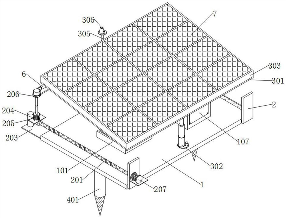
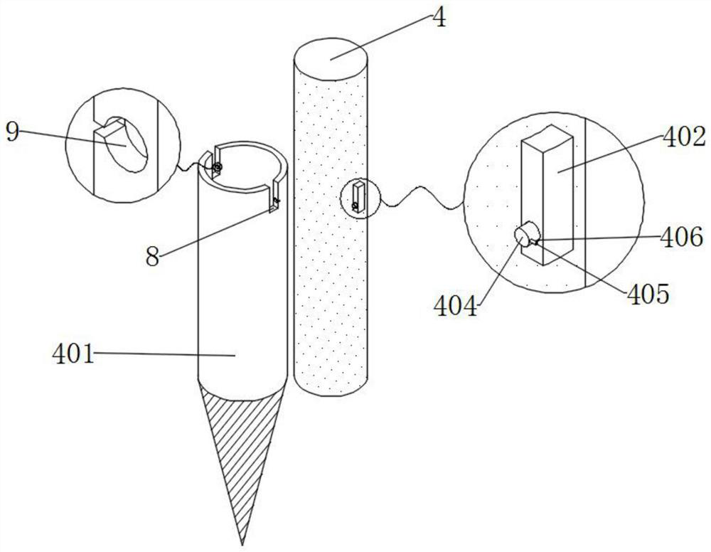
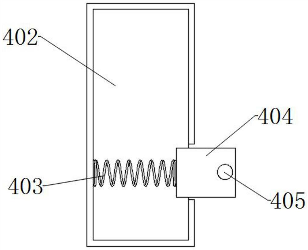
  • Centralized photovoltaic power station with stable output voltage
  • Centralized photovoltaic power station with stable output voltage
  • Centralized photovoltaic power station with stable output voltage

Examples


Embodiment Construction

[0039] The technical solutions in the embodiments of the present invention will be clearly and completely described below with reference to the accompanying drawings in the embodiments of the present invention. Obviously, the described embodiments are only a part of the embodiments of the present invention, rather than all the embodiments. Based on the embodiments of the present invention, all other embodiments obtained by those of ordinary skill in the art without creative efforts shall fall within the protection scope of the present invention.

[0040] In the description of the present invention, it should be noted that the terms "upper", "lower", "inner", "outer", "front end", "rear end", "two ends", "one end" and "the other end" The orientation or positional relationship indicated by etc. is based on the orientation or positional relationship shown in the accompanying drawings, which is only for the convenience of describing the present invention and simplifying the descrip...


PUM


Abstract

The invention discloses a centralized photovoltaic power station with stable output voltage, which comprises a base and a connecting plate, and is characterized in that the top of the base is provided with a storage frame, and the inner surface of the storage frame is provided with a shockproof plate; storage sleeves are installed at the four corners of the bottom wall of the storage frame, damping springs which are evenly distributed are installed on the bottom wall of the storage frame and located on the inner sides of the storage sleeves, insertion rods are installed in the storage sleeves in an embedded mode, photovoltaic inverters are installed at the tops of the insertion rods, and a storage battery is installed at the top of the base. The storage battery is located on one side of the photovoltaic inverter, and the photovoltaic inverter is electrically connected with the storage battery. And connecting plates which are arranged front and back are mounted on the front surface of the base. According to the invention, the base, the storage frame, the anti-vibration plate, the insertion rod and the photovoltaic inverter are arranged, and the damping springs and the anti-vibration plate cooperate with each other, so that the influence of vibration on the photovoltaic inverter in the use process can be reduced, and the stability of the output voltage of the power station is improved.

Description

technical field [0001] The invention relates to the technical field of photovoltaic power stations, in particular to a photovoltaic power station with a centralized output voltage stability. Background technique [0002] Solar photovoltaic power generation is a clean and environmentally friendly renewable energy. When using, multiple groups of solar photovoltaic panels are installed together, and then the power generation can be increased. Therefore, ground-based photovoltaic power plants often cover a large area, but Existing photovoltaic power plants still have major defects, therefore, a centralized photovoltaic power plant with stable output voltage is urgently needed. [0003] The defects of the existing photovoltaic power station are: [0004] 1. Patent document CN215198411U, which discloses a ground centralized photovoltaic power station cleaning device, including a plate frame, a pipe frame is installed with bolts at the top of the plate frame, a water pipe is insta...

Claims


Application Information

Patent Timeline
Patent Type & Authority Applications(China)
IPC IPC(8): H02S10/20H02S20/32H02S40/10F24S30/425
CPCH02S10/20H02S20/32H02S40/10F24S30/425Y02E70/30
Inventor 张劲张泽来
Owner 江苏富士特电气技术有限公司
Why Eureka
Eureka Blog
Learn More