
Manufacturing process of mining round-link chain

A technology for mining circular ring chain and manufacturing process, applied in the field of circular ring chain, can solve the problems of non-standard shape of ring chain, difficulty in removing teeth, broken chain, etc., to improve safety and service life, solve Fracture-prone defects, balanced force distribution

Pending Publication Date: 2022-05-27
王瑞丰
View PDF0 Cites 1 Cited by
  • Summary
  • Abstract
  • Description
  • Claims
  • Application Information

AI Technical Summary

Problems solved by technology

At present, the manufacturing process of mining circular link chains is mostly the same. Usually, high-strength alloy steel is used to cut the bar to make the bar, and the chain knitting machine is used to bend it into an oblong chain link composed of two straight arms and two arc-shaped ends. It is woven into the chain and finally welded to the joints. The overall strength is high. However, due to the large and uneven load on the mine-used round link chain during the working process, and the very harsh working environment, the broken chain may still inevitable
The existing statistical data show that in the case of chain breakage in mining round link chains, most of the link breakage is in the welding area. The reason is that although welding at the joint can obtain higher However, due to the material difference between the welding material and the base metal, the existence of welding defects, and the retention of residual stress, shallow cracks on the surface of the welded joints are prone to occur, and these shallow cracks are often difficult to be discovered in time during routine maintenance. The biggest safety hazard in operation is the main cause of fracture at the welded joint, especially when the motor is overloaded and the working load increases sharply, the welded joint with cracks is more likely to break than other parts of the chain link
[0004] The links of the existing round link chains for mines are usually bent from a single bar, and have a single joint structure. The joints are welded by flash butt welding, and the link will be subjected to upsetting force during the flash butt welding process. As for the overall longitudinal shortening, the two joints have a certain material loss due to the extrusion of the molten material on the joint surface, and the other straight arm without the joint will be shortened correspondingly through plastic deformation, and there is no material loss , which leads to the unequal size and shape of the two straight arms of the chain link; at the same time, it is difficult to pre-control the balance of the plastic deformation produced by the straight arms without joints during the upsetting process, and even local bending and local thickening may occur. In addition, during the upsetting process, the two arc-shaped ends are often compressed to a certain extent and the deformation state is difficult to control; the above factors lead to the chain of the circular link chain manufactured by the existing process. The shape of the ring is not standard and uniform, the force distribution of the chain link is not balanced during the working process, and the matching between the chain links and between the chain link and the chain teeth is poor, which is prone to unfavorable phenomena such as chain skipping, tooth beating, and tooth removal difficulties. Exacerbating the wear rate of mining circular link chains, which is also one of the important reasons why the existing circular link chains are easy to break and have a short service life

Method used


Image

  • Manufacturing process of mining round-link chain
  • Manufacturing process of mining round-link chain
  • Manufacturing process of mining round-link chain

Examples


Embodiment Construction

[0038] The manufacturing process of the mining circular chain disclosed in the present invention will be described in detail below with reference to the embodiments.

[0039] 23MnNiMoCr54 alloy steel is a commonly used mining chain steel. The mining circular chain made of it has the characteristics of good grinding performance, high fatigue times, high strength, strong impact resistance, and large bearing load. And the locking pin 2 is made of 23MnNiMoCr54 alloy steel.

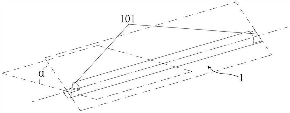
[0040] a. Prefabricate and pretreat the bar

[0041] like figure 1 As shown in the figure, according to the requirements of the type of mining ring chain to be produced, select the alloy steel round steel or wire rod of the corresponding specification, carry out straightening treatment, and use the precision bar shearing machine to cut the material to obtain the predetermined length of the bar. 1. Use a straightening machine to straighten the bar 1, so that the shape of the bar 1 tends to be a standard cylin...


PUM


Abstract

The invention relates to the field of round-link chains, and particularly discloses a manufacturing process of a mining round-link chain, which comprises the following steps: prefabricating a bar material, manufacturing two ends of the bar material into lap joint parts, forming locking grooves in the lap joint parts, prefabricating locking pins, bending the bar material into a special-shaped ring body consisting of two U-shaped parts, and the special-shaped ring body is connected with the chain ring, the two U-shaped parts are driven to relatively twist around the central axis of the bar middle section, the special-shaped ring body is deformed into the chain ring, the locking groove is in butt joint to form a locking hole, the locking pin is fixedly installed in the locking hole, and finally surface treatment, heat treatment and round-link chain forming post-treatment are sequentially conducted. In the process, the chain ring joints are fixedly connected through the locking pieces, the structure is stable and reliable, the defect that the welding positions of the previous joints are prone to breakage is overcome, longitudinal upsetting is not needed in the chain ring machining process, it is guaranteed that the size and shape of the ring chain woven into the same round-link chain are standard, stress of the chain ring is balanced in the working process, and the abrasion speed is reduced; and the transmission efficiency is improved.

Description

technical field [0001] The invention relates to the technical field of circular ring chains, in particular to a manufacturing process of a circular ring chain for mining. [0002] technical background [0003] The circular chain is widely used in mining machinery and equipment, and is often used as a traction component in important mining equipment such as coal plows, scraper conveyors, and loader. Production stops, and even lead to safety accidents, so it has extremely high requirements for safety. At present, the manufacturing process of mining circular chain is mostly the same. Usually, high-strength alloy steel is used to produce bar material, and a chain braiding machine is used to bend it into an oblong chain ring composed of two straight arms and two arc ends. It is incorporated into the chain, and finally the joints are welded, and the overall strength is high. However, due to the large and uneven load of the mining ring chain during the working process, and the work...

Claims


Application Information

Patent Timeline
Patent Type & Authority Applications(China)
IPC IPC(8): B21L1/04F16G15/12
CPCB21L1/04F16G15/12
Inventor 王瑞丰
Owner 王瑞丰
Learn More