Novel oil pipe joint device

A new type of oil pipe joint technology, applied in the direction of drill pipe, casing, drill pipe, etc., can solve the problems of difficult water drainage and gas recovery, weakened gas pressure, and inability to carry liquid.

Pending Publication Date: 2022-05-24
江苏孚杰高端装备制造(集团)股份有限公司
View PDF0 Cites 0 Cited by
  • Summary
  • Abstract
  • Description
  • Claims
  • Application Information

AI Technical Summary

Problems solved by technology

[0002] The oil pipe joint device is a supporting device for connecting oil pipes. Generally, in the early stage of gas well exploitation, due to the large stored energy and high pressure in the well, the gas will spray itself through the pipeline. Although water seeps out of the formation, it is also low permeability and can be passed through The method of gas-carrying liquid discharges the water without affecting the gas production. In the late stage of gas well exploitation, due to the reduction of stored energy and the gradual attenuation of the pressure in the well, although the gas will spray itself through the pipeline, the wellhead pressure is not very high, and the gas can no longer Carry liquid to discharge the water, as the water accumulates more and more, the pressure of the gas will gradually decay, and eventually the water will block the air inlet of the downhole pipeline, and the gas cannot enter the gas production pipeline, resulting in zero wellhead pressure and affecting Gas production, sometimes, in the entire gas production block is a typical "three-low" gas field with low permeability, low pressure, and low abundance, and the fluid accumulation in the well gradually increases. Drainage measures, but the gas production effect has not been very good, and it has become worse and worse, and finally there is no gas to be recovered, and it has become a long shut-in well. In addition, some blocks belong to water-bearing gas reservoirs, and the water-gas ratio reaches 5. : 1. Drainage and gas recovery are more difficult. Sometimes, in the early stage of mining, the formation is in a state of low water permeability, and in the later stage of mining, the formation will become a state of high water permeability, and the gas production rate is limited by the amount of liquid in production, resulting in the problem of weak production capacity , for the old gas wells that have been exploited for many years, due to the large water output in the well, the remaining 50% of the reserves are difficult to exploit, which seriously affects the recovery rate of the gas field. Relying on external power equipment such as mechanical pumping and jet pumps, tubing drainage and annular gas recovery are used. Due to the large cross-sectional area of ​​the annulus, liquid carrying production cannot be realized, and the speed of water accumulation is accelerated, causing the external power equipment to frequently start drainage, which consumes high costs. If the fracturing and gas production integrated string is used, the output is low. At 5,000 cubic meters per day, it is impossible to carry liquid to produce normally, and the gas production conditions will become worse and worse. Although small oil pipes and auxiliary bubble drainage measures can carry liquid to produce gas and improve the stable production capacity and recovery rate of gas wells, but with With the passage of time, the liquid-carrying capacity of the small tubing plus auxiliary foam drainage measures will gradually weaken, and will eventually lose its effect. As the progress of old well reconstruction continues to advance, the wellhead reconstruction with high water-gas ratio is also becoming more and more prominent. There will be more and more wellheads being transformed. If there is an effective process that can solve drainage, gas production, production increase, and stable production, it will be vigorously promoted in oil and gas fields. In recent years, drainage and gas recovery technology in the late stage of depletion mining No key breakthroughs have been made, and there is an urgent need for a gas production method that can fundamentally solve the problem of the remaining 50% reserves of new and old gas wells. For tight gas, shale gas, and coalbed methane, the storage pressure will gradually decrease and the water output will be slow. Slow increase, liquid carrying capacity decay, the problem of insufficient water drainage and gas recovery measures, with the continuous development of science and technology, people have higher and higher requirements for the manufacturing process of oil pipe joint devices
[0003] The existing oil pipe joint device has certain disadvantages in use. At present, the beam pumping unit is used as the external power equipment for pumping operations, and the water is discharged to the ground pipeline through the transportation of the oil pipe. The beam pumping unit was used in the early days Artificial lift equipment used for oil extraction, in oil fields, this kind of equipment generally exists, and it is also very convenient to use. It is feasible for the beam pumping unit to be used for pumping water, and the beam pumping unit uses pistons to work The principle is to pump formation water to the ground and discharge it through pipelines. The capacity of the piston to pump water at one time is limited. There is no continuity between each pumping and discharge, and there is an interval, that is, continuous drainage operations cannot be formed. When using the beam type In the early stage of the pumping unit, the rate of water discharge from the formation is still relatively slow. Although there is water seepage from the formation, it is also low-seepage water, and the pumping and discharge speed of the beam pumping unit can still keep up with the speed of water discharge from the formation. This This situation can be maintained for a period of time. In the later stage of using the beam pumping unit, the speed of formation water is increasing, and the speed of pumping and discharging of the beam pumping unit can no longer keep up with the speed of formation water. As the water accumulates More, the rise of the water level will slowly block the air inlet, causing the pressure of the gas to gradually weaken, and finally the water will block all the air inlets of the downhole pipeline, forming flooding. The gas cannot enter the annular pipeline at all, causing Wellhead pressure depletion, for water-bearing gas reservoirs with a water-gas ratio of 5:1, due to the huge water output, the beam pumping unit can no longer meet the requirements for pumping and discharging water. For old gas wells, due to the fast rate of formation water production, the beam pumping unit is not suitable for the drainage and gas recovery process of old gas wells in the later stage of depletion. For new and old wellheads of tight gas, shale gas, and coalbed methane, Due to the gradual reduction of reservoir pressure, the liquid carrying capacity gradually deteriorates, and the water outlet speed gradually increases. The effect of using beam pumping units for drainage operations is not very good. Due to the use of annulus gas production, the annulus area is relatively large. The gas can no longer carry the liquid to discharge the water, which will accelerate the rising speed of the water and cause the gas production conditions to become worse and worse. The beam pumping unit can no longer meet the drainage requirements. The use process has brought some adverse effects, for this reason, we propose a new type of oil pipe joint device

Method used


Image

  • Novel oil pipe joint device
  • Novel oil pipe joint device
  • Novel oil pipe joint device

Examples


Embodiment 1

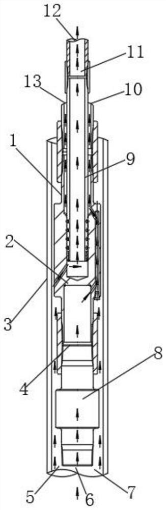
[0031] like Figure 1-5 As shown, a new type of oil pipe joint device includes an oil pipe joint main body 1, an oil cylinder 4 and a main passage hole 2 are arranged inside the oil pipe joint main body 1, an insertion rod 9 is arranged in the main passage hole 2, and an outer side of the oil pipe joint main body 1 is provided. A casing 3 is positioned, the top of the oil pipe joint body 1 is provided with a No. 1 air inlet 5, a water inlet 6 and a No. 2 air inlet 7, and the top of the oil pipe joint main body 1 is provided with a No. 1 water outlet 13 and a No. 2 water outlet 10, The top of the insertion rod 9 is provided with an air outlet 12 , and the oil cylinder 4 is provided with an electric submersible pump 8 .

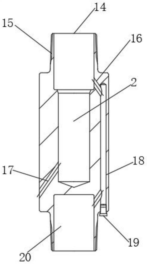
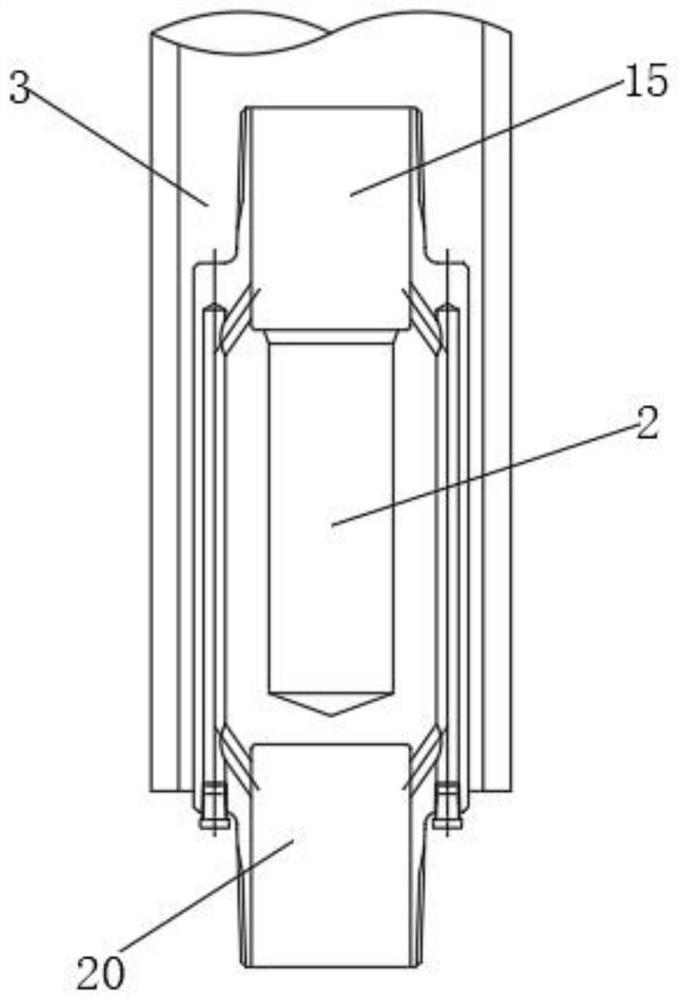
[0032] Further, the bottom position of the main passage hole 2 is provided with a No. 2 inclined hole 17, the top position of the main passage hole 2 is provided with a No. A screw 19 is installed at the bottom, and an upper oil pipe thread 15 and a lower oil ...

Embodiment 2

[0036] On the basis of Example 1, as figure 1 , 6 As shown, a new type of oil pipe joint device includes an oil pipe joint main body 1, an oil cylinder 4 and a main passage hole 2 are arranged inside the oil pipe joint main body 1, an insertion rod 9 is arranged in the main passage hole 2, and an outer side of the oil pipe joint main body 1 is provided. A casing 3 is positioned, the top of the oil pipe joint body 1 is provided with a No. 1 air inlet 5, a water inlet 6 and a No. 2 air inlet 7, and the top of the oil pipe joint main body 1 is provided with a No. 1 water outlet 13 and a No. 2 water outlet 10, The top of the insertion rod 9 is provided with an air outlet 12 , and the oil cylinder 4 is provided with an electric submersible pump 8 .

[0037] Further, when only water is produced and the well contains no gas, the input end of the oil cylinder 4 is provided with a water inlet groove 30 , and the output end of the oil cylinder 4 is provided with a water outlet groove 2...

Embodiment 3

[0039] On the basis of Example 1, as figure 1 , 7 As shown, a new type of oil pipe joint device includes an oil pipe joint main body 1, an oil cylinder 4 and a main passage hole 2 are arranged inside the oil pipe joint main body 1, an insertion rod 9 is arranged in the main passage hole 2, and an outer side of the oil pipe joint main body 1 is provided. The casing 3 is positioned, the top of the oil pipe joint main body 1 is provided with a No. 1 air inlet 5, a water inlet 6 and a No. 2 air inlet 7, and the top of the oil pipe joint main body 1 is provided with a No. 1 water outlet 13 and a No. 2 water outlet 10, The top of the insertion rod 9 is provided with an air outlet 12 , and the oil cylinder 4 is provided with an electric submersible pump 8 .

[0040] Further, what is transported is gas production, the formation pressure is very high, and there is a small amount of water in the well, and the gas can carry liquid to carry the water out of the wellhead. The water vapor...


PUM


Abstract

The invention discloses a novel oil pipe joint device which comprises an oil pipe joint body, an oil cylinder and a main channel hole are arranged in the oil pipe joint body, an insertion rod is arranged in the main channel hole, and a sleeve is positioned on the outer side of the oil pipe joint body. A first air inlet, a water inlet and a second air inlet are formed in the top of the oil pipe connector body. According to the novel oil pipe joint device, a water drainage and gas production channel is provided, the water drainage channel and the gas production channel do not interfere with each other, the trend of the water drainage channel and the reduction degree of the sectional area of the gas production channel are particularly considered in design, and it is ensured that in practical application, under the low-pressure condition, the oil pipe joint device is not prone to falling off. In other words, under the low-pressure condition, it is ensured that gas can carry liquid to be drained, the hidden danger of water can be eliminated, uninterrupted gas production can be ensured, stable production is ensured, and wide popularization prospects are achieved.

Description

technical field [0001] The invention relates to the field of oil pipe joints, in particular to a novel oil pipe joint device. Background technique [0002] The oil pipe joint device is a kind of support equipment for connecting oil pipes. Generally, in the early stage of gas well production, due to the large storage energy and high pressure in the well, the gas will self-spray through the pipeline. The gas-entrained method discharges water without affecting the gas production. In the late stage of gas well production, due to the reduction of stored energy and the gradual attenuation of the pressure in the well, although the gas will spontaneously blow through the pipeline, the pressure at the wellhead is not very high, and the gas can no longer be used. The liquid carries the water to discharge the water. As the water accumulates more and more, the pressure of the gas will gradually attenuate. Eventually, the water will block the air inlet of the downhole pipeline, and the g...

Claims


Application Information

Patent Timeline
IPC IPC(8): E21B17/18
CPCE21B17/18
Inventor 曾全胜孙国安刘丽佳王仕梁孙聚才彭朝文
Owner 江苏孚杰高端装备制造(集团)股份有限公司
Why Eureka
Try Eureka