Round wedge flowmeter

A flowmeter and wedge technology, applied in the field of flowmeters, can solve the problems of reducing the service life of throttling parts, the inability to realize the wedge flowmeter, and the lack of use value of the wedge flowmeter, so as to improve the stability and improve the use value. Effect

Pending Publication Date: 2022-05-13
上海库科自动化科技有限公司
View PDF0 Cites 0 Cited by
  • Summary
  • Abstract
  • Description
  • Claims
  • Application Information

AI Technical Summary

Problems solved by technology

[0003] During the use of the existing round wedge flowmeter, the distance between the first pressure-taking pipe and the second pressure-taking pipe is constant, and at the same time, the throttle is located between the first pressure-taking pipe and the second pressure-taking pipe In the process of measuring the pressure of the water body, the first set of pressure data is obtained after the water body flows through the first pressure measuring pipe. The water body cannot flow down smoothly. When this happens, the second pressure measuring tube located below cannot measure the second set of data, which will cause the circular wedge flowmeter to fail to realize its existing functions. At the same time, the first Excessive pressure between the pressure-taking pipe and the second pressure-taking pipe will easily cause excessive extrusion force on the throttling part, reduce the service life of the throttling part, and cause the circular wedge flowmeter to lack use value

Method used


Image

  • Round wedge flowmeter
  • Round wedge flowmeter
  • Round wedge flowmeter

Examples


Embodiment Construction

[0028] The following will clearly and completely describe the technical solutions in the embodiments of the present invention with reference to the accompanying drawings in the embodiments of the present invention. Obviously, the described embodiments are only some, not all, embodiments of the present invention.

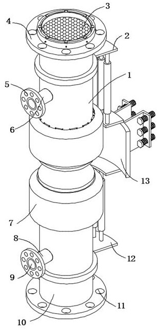
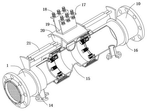
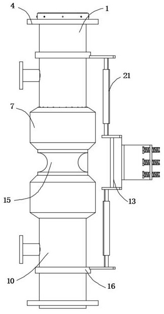
[0029] refer to Figure 1-4, a round wedge flowmeter, including an upstream straight pipe 1 and a downstream straight pipe 10, a throttling piece 15 is arranged between the upstream straight pipe 1 and the downstream straight pipe 10, and the outer walls of the throttling piece 15 at the upper end and the lower end are fixedly connected There is an outer ring plate 7, and the inner wall of the upper outer ring plate 7 is equidistantly fixedly connected with shaft blocks 29, and the outer walls of each adjacent two shaft blocks 29 are connected with the same connecting shaft 32 through bearings, and the outer walls of the connecting shaft 32 The sliding roller 31 is f...


PUM


Abstract

The invention belongs to the technical field of flow meters, in particular to a round wedge flow meter, and provides the following scheme that the round wedge flow meter comprises an upstream straight pipe and a downstream straight pipe, a throttling element is arranged between the upstream straight pipe and the downstream straight pipe, and outer ring plates are fixedly connected to the outer walls, located at the upper end and the lower end, of the throttling element; shaft blocks are fixedly connected to the inner wall of the outer ring plate located on the upper portion at equal intervals. The flow meter is provided with the installation self-adjusting assembly, when the flow meter is installed, the flow meter is installed at a designated position through installation bolts on an installation plate, the installation process is simple and convenient, after installation is completed, when the stretching pressure relief assembly conducts pressure adjustment in the upstream straight pipe and the downstream straight pipe, a telescopic rod on an end plate stretches out and draws back along with the telescopic rod, and the flow meter is installed conveniently. Therefore, the outside of the flow meter is stretched, dislocation deformation of the outside caused by long-term stretching of the inside of the flow meter is prevented, it is ensured that the stretching pressure relief assembly can work repeatedly, and the service life of the flow meter is prolonged.

Description

technical field [0001] The invention relates to the technical field of flow meters, in particular to a circular wedge flow meter. Background technique [0002] Flow measurement is one of the components of measurement science and technology. It is closely related to national economy, national defense construction, and scientific research. Doing this work well is of great importance to ensure product quality, improve production efficiency, and promote the development of science and technology. Especially in today's era of energy crisis and increasing automation of industrial production, the status and role of flowmeters in the national economy are more obvious; flowmeters are divided into differential pressure flowmeters, rotameters, Throttle flowmeter, slit flowmeter, volume flowmeter, electromagnetic flowmeter, ultrasonic flowmeter, turbine flowmeter and vortex flowmeter, etc. Classified by medium: liquid flowmeter, gas flowmeter, steam flowmeter and solid flowmeter. [00...

Claims


Application Information

Patent Timeline
IPC IPC(8): G01F1/36G01F15/12G01F15/18
CPCG01F1/36G01F15/18G01F15/125
Inventor 王兆军周革周玉琼
Owner 上海库科自动化科技有限公司
Why Eureka
Try Eureka