Processing and manufacturing method of heat exchanger

A processing and manufacturing heat exchanger technology, applied in the field of heat exchanger processing and manufacturing, can solve the problems of increasing the deformation of the upper tube sheet, affecting the dimensional accuracy of the upper tube sheet, and requiring extremely high flatness, etc., to achieve the effect of ensuring dimensional accuracy

Pending Publication Date: 2022-05-13
ZHANGHUAJI SUZHOU HEAVY EQUIP CO LTD
View PDF0 Cites 0 Cited by
  • Summary
  • Abstract
  • Description
  • Claims
  • Application Information

AI Technical Summary

Problems solved by technology

When the heat exchanger is working, it is necessary to install the membrane distributor on the upper plane of the upper tube sheet, so the flatness of the upper plane of the upper tube sheet is highly required. If the upper plane of the upper tube sheet is not flat, all the membranes will be damaged The devices cannot be on the same plane, so that some heat exchange medium enters the heat exchange tube first, and some heat exchange medium enters the heat exchange tube later, resulting in uneven heat exchange
[0004] The processing method of the heat exchanger in the prior art is as follows: firstly, the upper tube sheet is machined to make its size meet the design requirements, and then the top sub-joint and all other sub-joints are welded together to form a cylinder, and then the upper tube sheet is welded to the At the upper end of the cylinder, the lower tube sheet is welded to the lower end of the cylinder. Since the welding ring seam is located between the upper tube sheet and the cylinder, the heat generated by welding will affect the dimensional accuracy of the upper tube sheet; Disorder welding is used when the heat exchange tube and the upper tube sheet are welded. We found that this disordered welding will greatly increase the deformation of the upper tube sheet and affect the dimensional accuracy of the upper tube sheet.

Method used


Image

  • Processing and manufacturing method of heat exchanger
  • Processing and manufacturing method of heat exchanger

Examples


Embodiment Construction

[0012] The manufacturing method of a heat exchanger according to the present invention will be further described in detail through specific examples below.

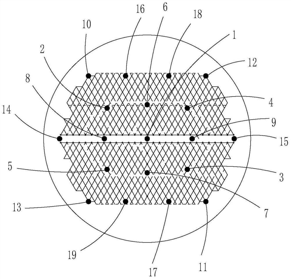
[0013] A processing and manufacturing method for a heat exchanger, comprising the following steps: A. The cylinder body includes a top nipple and several other nipples arranged below the top nipple. The length of the top nipple is 400 mm. The lower plane of the plate, the welding groove of the top sub-section and the welding groove of the upper tube sheet are machined; B. Then, the upper tube sheet and the top sub-joint are welded, flaw detected and heat treated to obtain the upper tube sheet assembly; C. Then machine all the processing surfaces of the upper tube plate assembly except the lower plane of the upper tube plate. After machining, the thickness of the upper tube plate is the design value of the upper tube plate thickness + 2mm; D. Next, carry out machining on the upper tube plate Drill holes to form several upp...


PUM

PropertyMeasurementUnit
lengthaaaaaaaaaa

Abstract

The invention relates to a machining and manufacturing method of a heat exchanger. The machining and manufacturing method comprises the following steps that A, the lower plane of an upper tube plate is machined; b, performing assembly welding and flaw detection on the upper tube plate and the top pup joint; c, all the machining faces, except for the lower plane of the upper tube plate, of the upper tube plate assembly are machined; d, drilling the upper tube plate and the lower tube plate; e, a plurality of other pup joints are subjected to assembly welding, flaw detection and heat treatment; f, the upper tube plate assembly and the short section assembly are installed, welded and subjected to flaw detection; g, mounting a pull rod, a sleeve and a baffle plate in the barrel; h, mounting a heat exchange tube in the barrel in a penetrating manner; i, assembling the lower tube plate; j, the tube heads are welded to the upper tube plate and the lower tube plate respectively, and the following sequence is adopted during welding: the tube heads of the heat exchange tubes adjacent to the pull rods are welded firstly, and then the remaining tube heads are subjected to regional cross symmetric welding; k, mechanically cutting off the extension part of the pipe head; l, performing local heat treatment; and M, finally installing a sealing head. Therefore, the size precision of the upper tube plate is greatly improved.

Description

【Technical field】 [0001] The invention relates to the field of chemical machinery, in particular to a method for processing and manufacturing a heat exchanger. 【Background technique】 [0002] A heat exchanger is an energy-saving device that transfers material heat between two or more fluids at different temperatures. It transfers heat from a fluid with a higher temperature to a fluid with a lower temperature, so that the temperature of the fluid reaches the specified value of the process. Indicators to meet the needs of process conditions, but also one of the main equipment to improve energy efficiency. The heat exchanger industry involves nearly 30 industries such as HVAC, pressure vessels, reclaimed water treatment equipment, chemical industry, and petroleum. [0003] The vertical heat exchanger is one of the heat exchangers, that is, its installation direction is vertical installation, and the cold and hot fluids in it mainly flow vertically as a whole. Vertical heat exc...

Claims


Application Information

Patent Timeline
Patent Type & Authority Applications(China)
IPC IPC(8): F28F9/26F28F9/00F28F9/18B23P15/26
CPCF28F9/26F28F9/00F28F9/18B23P15/26F28F2275/06
Inventor 谢玉超王胜余强
Owner ZHANGHUAJI SUZHOU HEAVY EQUIP CO LTD
Why Eureka
Try Eureka