Oil and gas transportation pipeline electric heating thermal management system based on renewable energy sources and CO2 energy storage

A renewable energy and thermal management system technology, applied in the field of electric heating thermal management system for oil and gas transportation pipelines, can solve the problems of wasting electric energy, insufficient heating effect, waste of resources, etc., to avoid volatility and intermittency, reduce The heating effect is not good, and the effect of reducing economic costs

Active Publication Date: 2022-05-13
DALIAN UNIV OF TECH
View PDF8 Cites 1 Cited by
  • Summary
  • Abstract
  • Description
  • Claims
  • Application Information

AI Technical Summary

Problems solved by technology

However, only the spiral winding method is used in the whole process, which greatly increases the resistance of the electric heating cable, and a large amount of electric energy is wasted during long-term use, which increases the production cost, and there is no effective heat preservation structure at the bottom of the deep sea, and the heat generated by heating is easily dissipated. In the deep sea, the heating effect is not obvious enough, and even loses the heating effect under extreme conditions. Not only will it not play the role of heating, but it will lead to a waste of resources
In addition, the existing electric heating belt is laid on the transportation pipeline throughout the whole process, and the heating control device is not perfect enough, so it is impossible to heat the transportation pipeline to different degrees in unblocked, easily blocked or blocked positions, which not only wastes Electric energy also reduces the scope of application of electric heating cables

Method used


Image

  • Oil and gas transportation pipeline electric heating thermal management system based on renewable energy sources and CO2 energy storage
  • Oil and gas transportation pipeline electric heating thermal management system based on renewable energy sources and CO2 energy storage
  • Oil and gas transportation pipeline electric heating thermal management system based on renewable energy sources and CO2 energy storage

Examples


Embodiment Construction

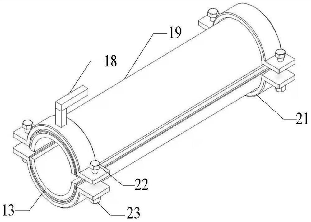
[0038]The specific implementation manners of the present invention will be further described below in conjunction with the accompanying drawings and technical solutions.

[0039] Such as Figure 1-3 As shown, this embodiment discloses a 2 Electric heating thermal management system for oil and gas transportation pipelines with energy storage, including renewable energy power supply devices, CO 2 Energy storage device 3, control device 4, early warning device 5, remote operation device 6, electric heating device for oil and gas transportation pipelines.

[0040] Wherein, the energy source of the renewable energy power supply device includes but not limited to solar energy, wind energy or ocean current energy at sea, and the wind power supply device 1 and the solar power supply device 2 are included in this embodiment.

[0041] CO 2 The energy storage device 3 is coupled with the renewable energy power supply device, CO 2 The energy storage device 3 sends the stored electric ...


PUM


Abstract

The invention discloses an oil and gas transportation pipeline electric heating thermal management system based on renewable energy sources and CO2 energy storage. The system comprises a renewable energy source power supply device, a CO2 energy storage device, a control device, an early warning device, a remote operation device and an oil and gas transportation pipeline electric heating device. According to the system, data values fed back by data acquisition equipment arranged in a pipeline are transmitted to an early warning device through a control device, the early warning device can feed back the data values to the control device and a remote operation device in two modes after analyzing and processing the data values, and heating amounts of different degrees are generated for oil and gas transportation pipelines at different positions in different modes. Graded and distributed management control can be carried out on the oil and gas transportation pipeline at the positions which are not blocked, easy to block and blocked in a targeted mode. The renewable energy source power supply device is coupled with the CO2 energy storage device, the electric power cost for maintaining the temperature of the pipeline is greatly reduced, the problem that the use amount of an inhibitor in the oil and gas transportation pipeline is large is indirectly solved or relieved, and bright prospects are achieved.

Description

technical field [0001] The invention belongs to the technical field of flow safety assurance of oil and gas transportation pipelines, and specifically relates to a system based on renewable energy and CO 2 Energy storage oil and gas transportation pipeline electric heating thermal management system. Background technique [0002] At present, deep-sea oil and gas represents a major trend in oil development in the world today. The pipes used to transport oil and gas are generally steel pipes, which are welded to long-distance pipelines with connecting devices such as flanges and tees, and valves and other equipment are used for opening and closing control and flow regulation. However, during the long-distance transportation of deep-sea pipelines, due to high pressure and low temperature conditions, solids represented by wax crystals and hydrates are easily formed inside the pipeline, especially in the pipeline bends and connecting valves. With the continuous loss of heat insid...

Claims


Application Information

Patent Timeline
Patent Type & Authority Applications(China)
IPC IPC(8): F16L53/38F16L59/02F17D3/01F17D5/00F17C1/00
CPCF16L53/38F17D3/01F17D5/00F17D5/005F17C1/00F16L59/02F17C2221/013F17C2270/05Y02E70/30H05B1/0244F16L53/34F03D9/25F01K3/00F01K3/186H05B1/00
Inventor 陈聪宋永臣王喜陈哲锐孙菁悦刘瑜张毅杨明军赵佳飞刘卫国秦妍凌铮蒋兰兰张伦祥
Owner DALIAN UNIV OF TECH
Why Eureka
Try Eureka