Eureka AIR delivers breakthrough ideas for toughest innovation challenges, trusted by R&D personnel around the world.

Sintering furnace type cooling device

A technology of cooling device and mine furnace, which is applied to furnaces, furnace components, processing discharged materials, etc., can solve the problems of low waste heat utilization efficiency, fluctuation of waste heat parameters, and large cooling energy consumption, so as to reduce the amount of returned ore and ore particles. Uniform and stable temperature, the effect of ensuring strength

Active Publication Date: 2013-08-07
CITIC HEAVY INDUSTRIES CO LTD +1
View PDF6 Cites 34 Cited by
  • Summary
  • Abstract
  • Description
  • Claims
  • Application Information

AI Technical Summary

Problems solved by technology

[0004] The technical problem to be solved by the present invention is to provide a sinter furnace type cooling device, which can maximize the recovery and utilization efficiency of sinter waste heat on the premise of ensuring or improving the quality of sinter and reducing the amount of returned ore, and solves the current Problems such as waste heat parameter fluctuations, system air leakage, low waste heat utilization efficiency and high cooling energy consumption exist in the process of high-temperature sinter cooling and waste heat utilization, so as to improve the overall operating environment

Method used


Image

  • Sintering furnace type cooling device
  • Sintering furnace type cooling device

Examples


Embodiment Construction

[0017] The present invention will be further described in detail below in conjunction with the accompanying drawings and specific embodiments.

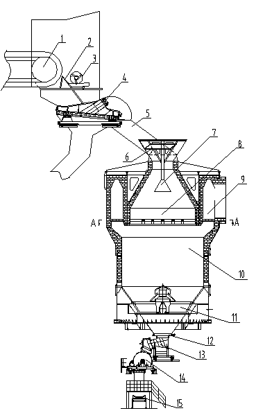
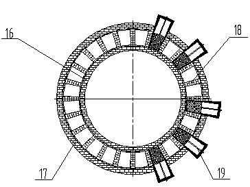
[0018] Such as figure 1 and figure 2 As shown, the sinter furnace type cooling device includes a sintering machine 1, a single roll crusher, a thermal vibrating screen 4, a chute 5, a material distribution device 7, a cooling furnace, an air distribution device 11, a discharge device and a belt conveyor 15. The outlet of the sintering machine 1 is provided with a single-roll crusher. The single-roll crusher includes a grate plate 2 and a crushing roller 3. The grate plate 2 is arranged obliquely, and the crushing roller 3 is vertically arranged directly above the grate plate 2; There is a thermal vibrating screen 4 arranged obliquely at the outlet; the thermal vibrating screen 4 is connected to the entrance of the chute 5, the outlet of the chute 5 is connected to the furnace mouth of the cooling furnace, the material distribution d...


PUM

PropertyMeasurementUnit
angleaaaaaaaaaa

Abstract

A sintering furnace type cooling device relates to the technology field of sintering cooling devices. An outlet of a sintering machine is provided with a single roll crusher; an outlet of the single roll crusher is provided with a hot sinter screen; the hot sinter screen is connected with an inlet of a chute; an outlet of the chute is connected with a furnace opening of a cooling furnace; a distributing device is arranged inside the furnace opening of the cooling furnace; a ventilation device is arranged at the bottom of the cooling furnace; a discharging device is connected under the ventilation device; a belt conveyer is arranged under the discharging device; the cooling furnace comprises a pre-store area which is arranged on the upper portion, a cooling area which is arranged on the lower portion and an annular flue area which is arranged on the periphery of the pre-store area; radial supporting columns which are integrally and radially distributed are arranged at the bottom of the annular flue area; a high-temperature flue gas adjustment plate is coated on two adjacent radial supporting columns; and the high-temperature flue gas adjustment plate is capable of sliding along a diametrical direction of the annular flue. The sintering furnace type cooling device has the advantages of effectively overcoming the defects that an existing sintering cooling system is serious in air infiltration and low in waste heat utilization rate, achieving efficient heat replacement, improving the temperature of the flue gas and reducing energy consumption in cooling.

Description

technical field [0001] The invention relates to the technical field of sinter cooling equipment, in particular to a sinter furnace type cooling device. Background technique [0002] my country is a country that consumes a lot of energy. In order to vigorously promote energy-saving and environmental protection technologies and improve the comprehensive utilization efficiency of energy, the country has proposed a series of encouraging and preferential policies. The iron and steel industry is a large energy consumer in my country, accounting for about 15% of the total energy consumption in the country. In the process of iron and steel production, the energy consumption of the sintering process ranks second, and the sensible heat of sintering production in sintering production accounts for more than 40% of the total heat consumption. Energy saving in sintering is very important. Efficient recycling and utilization of sensible heat of sintering is an effective way to improve energ...

Claims


Application Information

Patent Timeline
Patent Type & Authority Applications(China)
IPC IPC(8): F27D15/02
Inventor 乔文存俞章法彭岩程波郭存红李建强吴锦平
Owner CITIC HEAVY INDUSTRIES CO LTD
Why Eureka
Eureka Blog
Learn More