
Self-driven wind power generation system

A wind power generation system and self-driving technology, which is applied in the direction of wind power generation, wind power engine, wind power motor combination, etc., can solve the problem that the pitch angle cannot be driven automatically, and achieves the self-driven start-up process, light top, and good stability Effect

Inactive Publication Date: 2022-05-13
洪少豪
View PDF0 Cites 0 Cited by
  • Summary
  • Abstract
  • Description
  • Claims
  • Application Information

AI Technical Summary

Problems solved by technology

[0004] Based on the technical problem that the existing generator set cannot realize the self-driven pitch angle under the condition of light wind, the present invention proposes a self-driven wind power generation system

Method used


Image

  • Self-driven wind power generation system
  • Self-driven wind power generation system
  • Self-driven wind power generation system

Examples


Embodiment 1

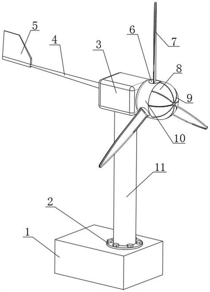
[0029] refer to Figure 1-Figure 3 , a self-driven wind power generation system, including a wind mechanism, a transmission mechanism and a power generation mechanism, the wind mechanism includes a transmission case 3 arranged horizontally, a blade mechanism is arranged at one end of the transmission case 3, and a blade mechanism is arranged at the other end of the transmission case 3 There is a tail rudder mechanism, the transmission mechanism includes a vertically arranged fixed cylinder 11, the bottom of the transmission case 3 is socketed with the top of the circumferential inner wall of the fixed cylinder 11 through bearings, and the circumferential position of the blade mechanism is provided with three circumferential arrays of pitch-changing mechanisms , the generating mechanism includes a generator base 1 arranged horizontally, and the same fixing flange 2 is fixed between the generator base 1 and the fixing cylinder 11 by bolts.

[0030] Further, the blade mechanism i...

Embodiment 2

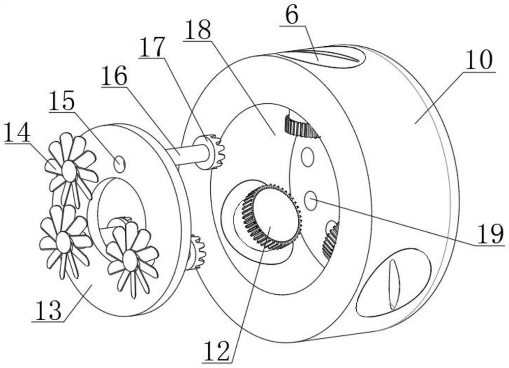
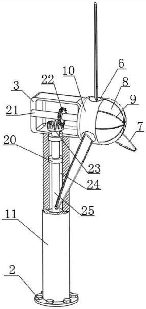
[0039] refer to Figure 1-Figure 7 , a self-driven wind power generation system, including a wind mechanism, a transmission mechanism and a power generation mechanism, the wind mechanism includes a transmission case 3 arranged horizontally, a blade mechanism is arranged at one end of the transmission case 3, and a blade mechanism is arranged at the other end of the transmission case 3 There is a tail rudder mechanism, the transmission mechanism includes a vertically arranged fixed cylinder 11, the bottom of the transmission case 3 is socketed with the top of the circumferential inner wall of the fixed cylinder 11 through bearings, and the circumferential position of the blade mechanism is provided with three circumferential arrays of pitch-changing mechanisms , the generating mechanism includes a generator base 1 arranged horizontally, and the same fixing flange 2 is fixed between the generator base 1 and the fixing cylinder 11 by bolts.

[0040] Further, the blade mechanism i...


PUM


Abstract

The invention belongs to the technical field of wind power generation, particularly relates to a self-driven wind power generation system, and aims to solve the problem that an existing generator set cannot realize variable pitch angle self-driving under the condition of breeze, the following scheme is provided: the self-driven wind power generation system comprises a wind power mechanism, a transmission mechanism and a power generation mechanism, a paddle mechanism is arranged at one end of the transmission case, a tail vane mechanism is arranged at the other end of the transmission case, and the transmission mechanism comprises a vertically-arranged fixing cylinder. Under the condition of breeze, the variable pitch mechanism of the system device works, air inlet breeze is obtained through the air inlet grid holes, high-flow-speed wind power is generated through the air inlet faces of the inner fan blades, the angle of the blades becomes smaller through linkage, a larger windward face is obtained, and therefore self-driven rotation can be generated under the breeze, and the power generation process is conducted.

Description

technical field [0001] The invention relates to the technical field of wind power generation, in particular to a self-driven wind power generation system. Background technique [0002] Wind power generation refers to the conversion of wind kinetic energy into electrical energy. Wind is a pollution-free energy source. The use of wind power generation is very environmentally friendly and can generate huge electric energy. Therefore, more and more countries pay more attention to wind power generation. As a As a clean and renewable energy, more and more countries in the world pay more and more attention to it. It has huge reserves. The wind has been used by people for a long time—mainly through windmills to pump water and grind flour. Now, people are interested in how to The wind is used to generate electricity. In the wind power generation in the prior art, domestic wind power generation equipment is also often used. [0003] The existing domestic wind power generation equipme...

Claims


Application Information

Patent Timeline
Patent Type & Authority Applications(China)
IPC IPC(8): F03D9/25F03D1/06F03D7/02F03D15/00
CPCF03D9/25F03D1/0675F03D7/0224F03D15/00Y02E10/72
Inventor 洪少豪
Owner 洪少豪
Learn More