
Screw threaded fastener and fastening system

a threaded fastener and threaded technology, which is applied in the direction of screws, sheet joining, roof coverings, etc., can solve the problems of aforementioned type of fastening failure and inability to secure or strengthen the fastening assembly in the process, and achieve the effect of rapid fastening of one member and high resistance to failur

Inactive Publication Date: 2001-02-13
W A DEUTER
View PDF14 Cites 38 Cited by
  • Summary
  • Abstract
  • Description
  • Claims
  • Application Information

AI Technical Summary

Benefits of technology

It is an object of the present invention to provide a screw threaded fastener having a modified thread form which enables relatively rapid fastening of one member to another and which provides a secure fastening between those members. It is a further object of the invention to provide a fastening system which is highly resistant to failure.
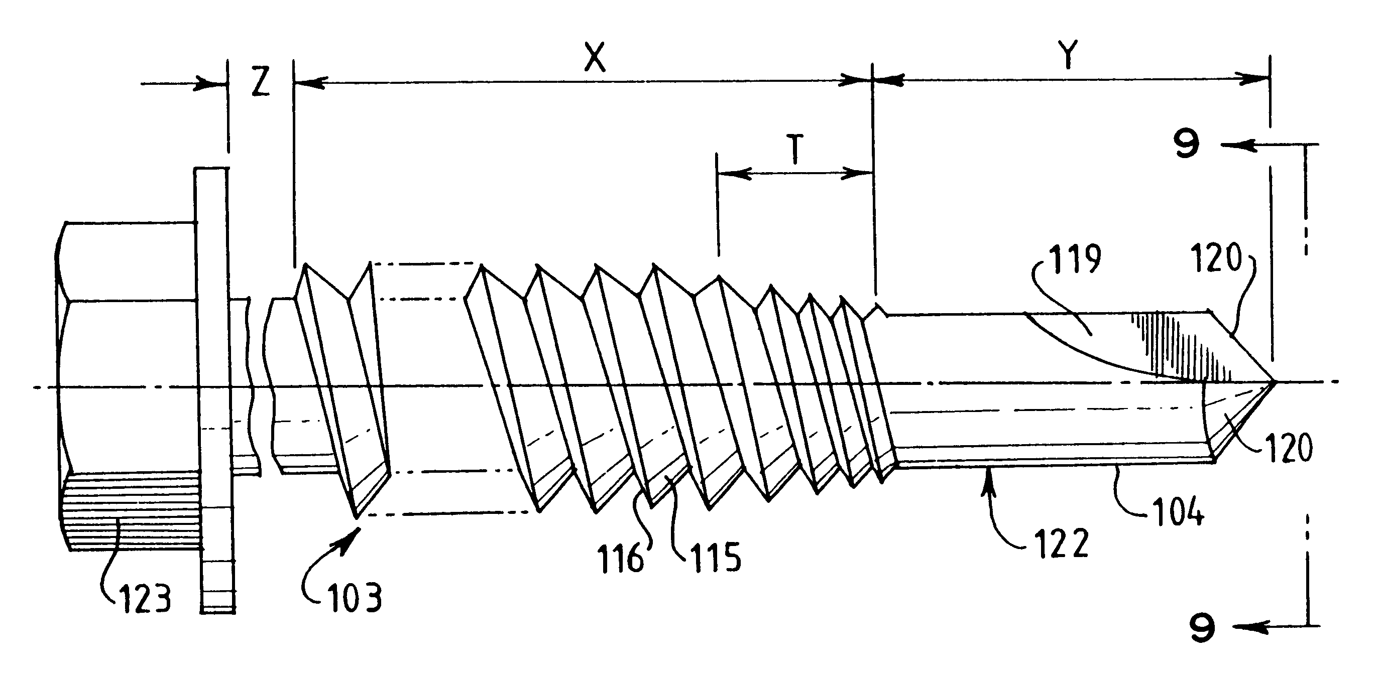
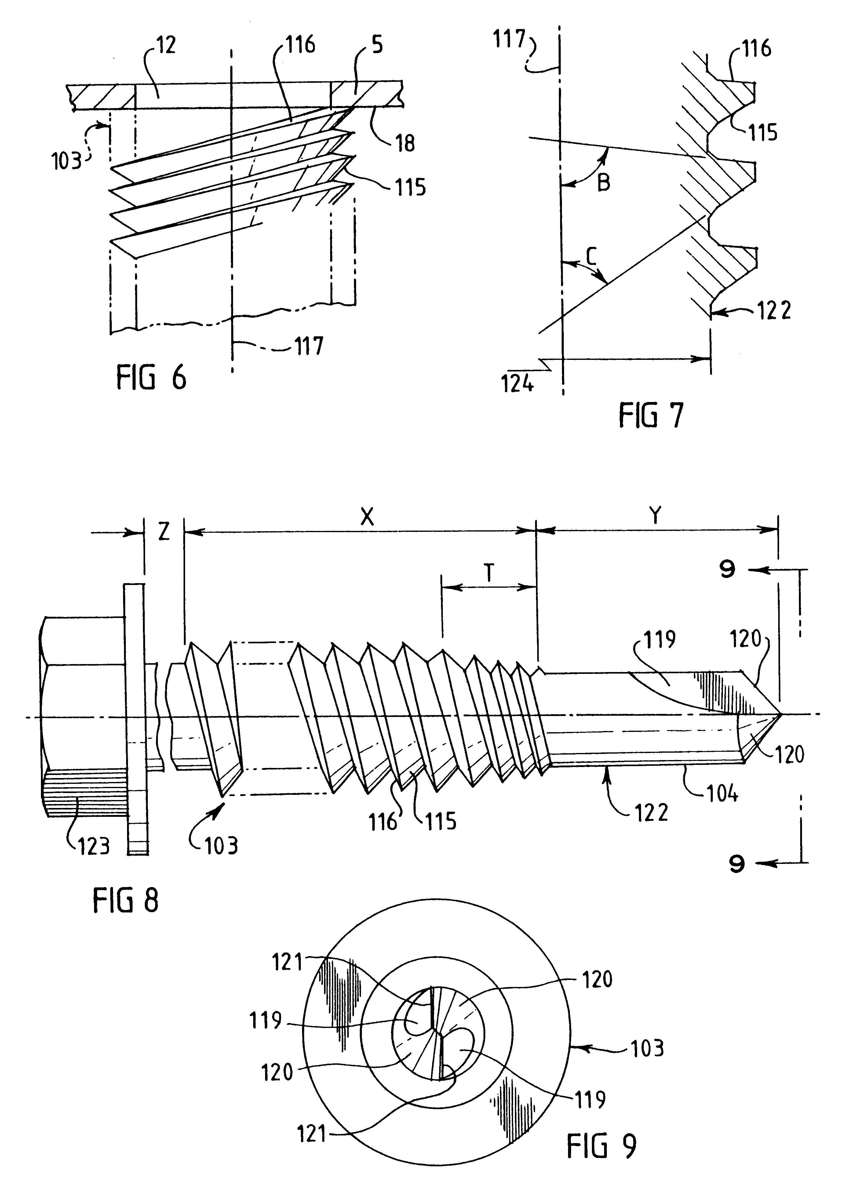
A screw threaded fastener according to the invention is characterized in that the angle subtended between the longitudinal axis of the screw and the trailing flank of the screw thread is greater than the corresponding angle subtended between said longitudinal axis and the leading flank of the screw thread and wherein the trailing flank angle is closer to 90.degree. than is the leading flank angle. This angular disposition of the trailing flank relative to the leading flank of the screw thread, in use of the fastener, reduces the angle between the trailing flank and the adjacent thin metal section of a batten surrounding the fastener. This has a decreased distorting effect on the thin metal batten under pull out loads on the fastener to that produced by the screw thread of a conventional fastener wherein the leading and trailing flanks slope at substantially the same angle relative to the longitudinal axis of the fastener.

Problems solved by technology

Selection of such a fastener from the available range of such fasteners is largely determined by the speed with which the fastening operation can be achieved, but the security or strength of the fastened assembly may be compromised in the process.
Fastenings of the aforementioned kind have been found to fail particularly in situations involving relatively high wind loading.
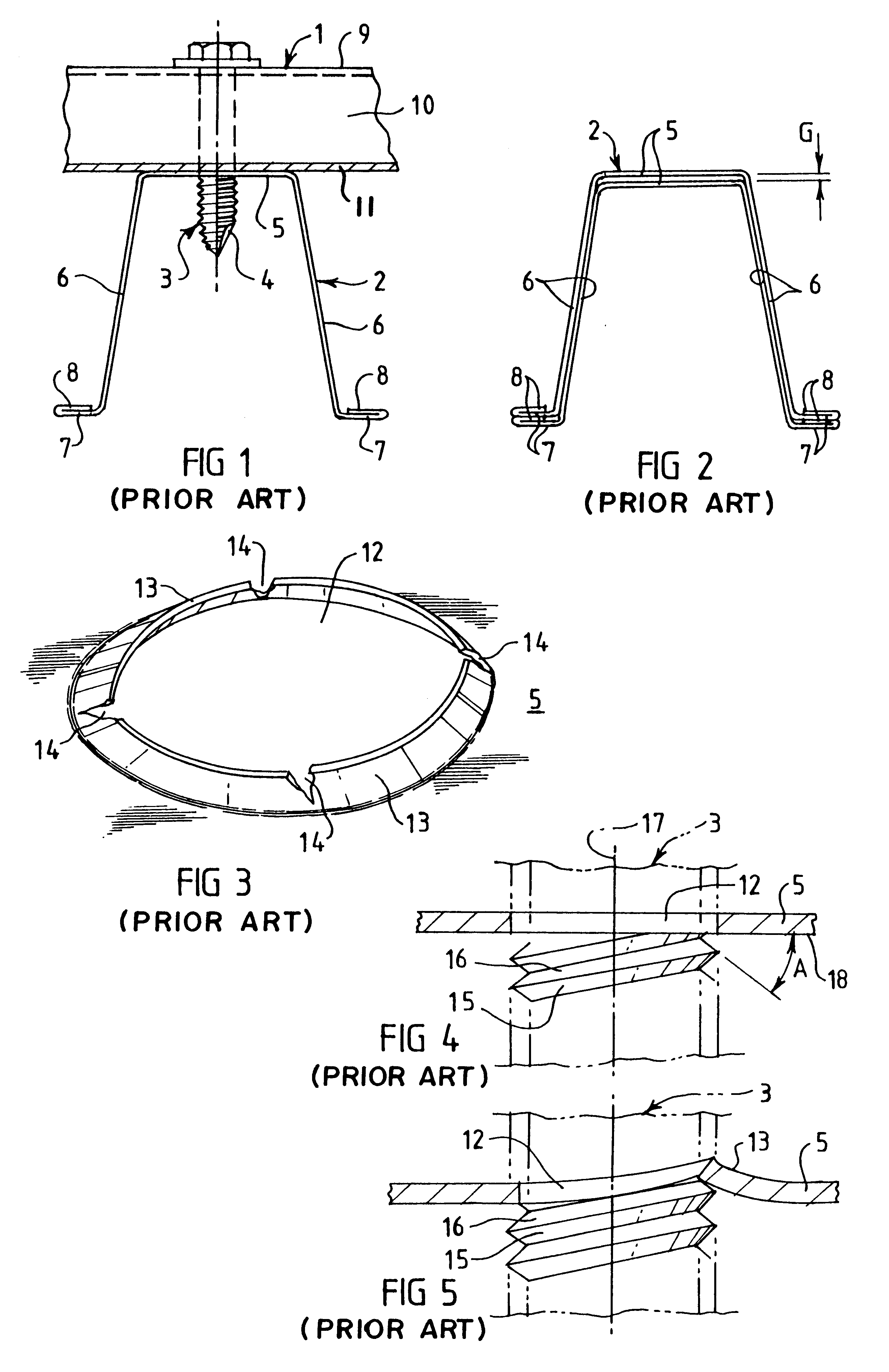
It has been discovered that such failures are due at least in part to the distorting effect of the thread form of conventional fasteners on the thin metal battens.

Method used


Image

  • Screw threaded fastener and fastening system
  • Screw threaded fastener and fastening system
  • Screw threaded fastener and fastening system

Examples


Embodiment Construction

FIG. 1 illustrates a typical fastening system in which a sheet 1 of roofing material is secured to a thin metal batten 2 by means of a conventional self-tapping screw threaded fastener 3 having a drilling tip 4. The batten 2 is of a typical construction having a body of inverted channel configuration comprising a top wall 5 and a pair of spaced side walls 6. A laterally extending flange 7 is provided along the lower edge of each side wall 6 and, as shown, it is usual to turn back the outer edge 8 of the flange 7 for strengthening purposes. As is well known, sheets of roofing material are generally corrugated or otherwise formed to have alternating ribs and valleys of various shapes. The roofing sheet 1 shown in FIG. 1 is of that construction and as shown the fastener 3 passes through the upper wall 9 of a rib 10 whereas the lower wall 11 of a valley bears against the batten top (support) wall 5.

Battens 2 are generally supplied in standard lengths and it will occur that two or more b...


PUM


Abstract

A screw threaded fastener (103) has an elongate shank (122) with a drilling tip (104) at one end and a head (123) at the other end. A screw thread extends along at least a part of the length of the shank (122). The trailing flank (116) of the thread subtends an angle (B) relative to the axis (117) of the fastener which approaches 90° and is greater than the angle (C) subtended by the leading flank (115). The screw is for use in fixing sheets of material a1 to thin metal battens (5) and the angle between the trailing flank (116) and the adjacent thin metal section (18) of the batten (9), being reduced in comparison to a conventional thread form, lessens the distorting effect of the thread on the batten (9) under relatively high pull-out loads.

Description

This invention relates to the fastening of material to thin metal structures. It will be convenient to hereinafter describe the invention with particular reference to the fixing of roofing or cladding material to battens of thin material section, but the invention has wider application. The invention is concerned with fastening systems of the foregoing kind and is also concerned with a fastening screw for use in such a system.In the context of this specification the expression "thin metal" is to be understood as referring to metal having a thickness not significantly greater than one millimeter, and more generally in the range 0.4 to 0.8 mm.It is common practice to secure metal roofing material to thin metal battens by means of self-tapping threaded fasteners of the kind having a drilling tip. Selection of such a fastener from the available range of such fasteners is largely determined by the speed with which the fastening operation can be achieved, but the security or strength of t...

Claims


Application Information

Patent Timeline
Patent Type & Authority Patents(United States)
IPC IPC(8): F16B25/10F16B25/00E04B1/38E04D3/365F16B5/02
CPCF16B25/0021F16B25/0047F16B25/103
Inventor ROBERTS, DAVID JAMES ALEXANDERDONEDDU, MARK
Owner W A DEUTER
Learn More