
Structure for preventing tile from being separated from tile base

A technology of separating structures and pads, which is applied in the direction of sliding contact bearings, bearings, bearing components, etc., can solve the problems of pad edge drop, wear pad surface and thrust plate, and affect the work and life of thrust bearings, so as to avoid The effect of increased pressure

Pending Publication Date: 2022-04-29
HARBIN ELECTRIC POWER EQUIP
View PDF0 Cites 0 Cited by
  • Summary
  • Abstract
  • Description
  • Claims
  • Application Information

AI Technical Summary

Problems solved by technology

When the cooling water comes to the contact between the baffle plate and the tile base, the impact and accumulation of the cooling water will cause pressure in the local area. At this time, the pressure on the non-working surface of the tile is greater than the pressure on the working surface of the tile, causing the non-working surface of the tile in the upstream direction to separate from the tile base and Tilting, the rotating thrust plate hits the partially tilted working surface of the tile, causing particles to fall from the edge of the tile, and then wears the tile surface and the thrust disk, affecting the work and life of the thrust bearing; in severe cases, it may reduce the idle time or completely The main rotor is stuck, endangering the safety of nuclear power plants

Method used


Image

  • Structure for preventing tile from being separated from tile base
  • Structure for preventing tile from being separated from tile base
  • Structure for preventing tile from being separated from tile base

Examples


Embodiment Construction

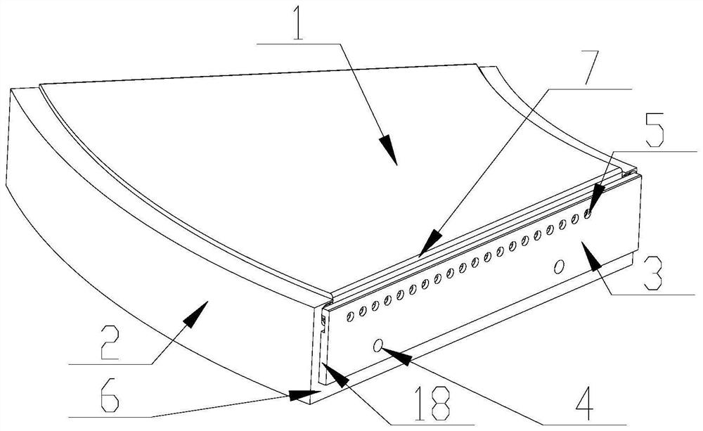
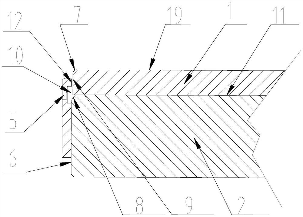
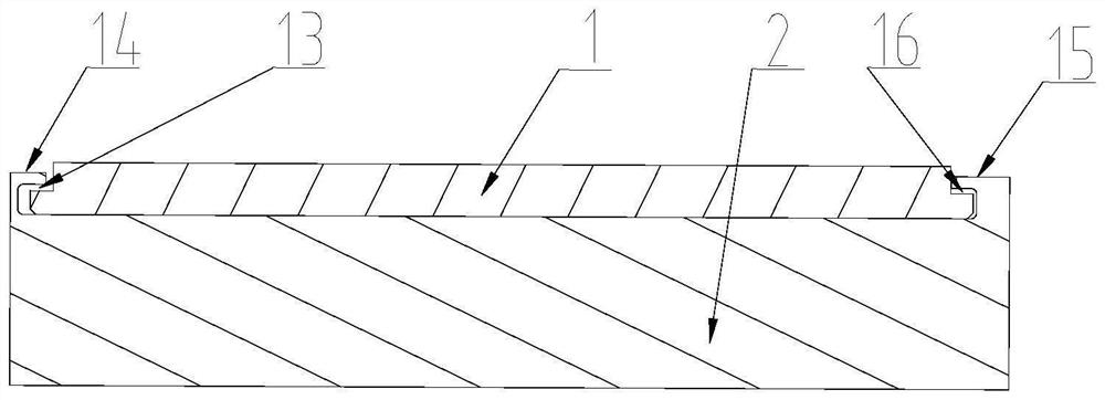
[0014] Such as image 3 As shown, a structure for preventing tiles from being separated from the tile base. There are first limiting steps 14 and second limiting steps 15 on both sides of the tile base 2. The tile 1 is located on the bottom surface of the tile base 2 and the first limiting steps 14 In the space formed with the second limiting step 15, there is an axial installation gap 13 between the first limiting step 14 of the tile 1 and the tile base 2, and there is an axial installation gap between the second limiting step 15 of the tile 1 and the tile base 2 16. Such as figure 1 As shown, the baffle 3 is fixed on the side 6 of the tile base 2 through the mounting hole 4 . Such as figure 2 As shown, the working surface 19 of the tile is provided with a rounding 7 facing the flow, the baffle plate 3 and the tile base 2 have a radial gap 12, the flow pressure relief hole 5 is facing the contact surface 11 between the tile 1 and the tile base 2, and the tile base 2 has a...


PUM


Abstract

The invention relates to a structure for preventing a tile from being separated from a tile base, a first limiting step (14) and a second limiting step (15) are arranged on two sides of the tile base (2), the tile (1) is positioned on the bottom surface of the tile base (2) and in a space formed by the first limiting step (14) and the second limiting step (15), and an axial mounting gap (13) exists between the tile (1) and the first limiting step (14) of the tile base (2). An axial mounting gap (16) is formed between the tile block (1) and the first limiting step (15) of the tile base (2); the baffle (3) is fixed on the side surface (6) of the tile base (2) through the mounting hole (4), and a radial gap (12) is formed between the baffle (3) and the tile base (2); the baffle (3) is provided with a cooling water collecting groove (10), and the collecting groove (10) is provided with a plurality of through-flow pressure relief holes (5). By applying the fluid dynamics principle, the tile blocks can be effectively prevented from being separated from the tile bases under fluid impact, upwarp of the incident flow sides of the tile blocks is prevented, impact with a rotating thrust disc is avoided, and safe operation of a nuclear main pump is ensured.

Description

technical field [0001] The invention relates to a structure for preventing tiles from being separated from tile bases, which is applied in the field of nuclear reactor coolant pump water lubricating bearings. Background technique [0002] Nuclear power has brought clean energy to human beings. The nuclear power plant reactor coolant pump is the only rotating equipment in the primary circuit of the nuclear power plant. Its reliable operation is very important to the safety of the nuclear power plant. The third-generation nuclear power coolant pump uses a shielded motor or a wet winding motor, and uses a water-lubricated thrust bearing to withstand the axial force. The tile block is limited in the circumferential direction, and the lower side of the baffle is attached to the tile base. Due to the requirements of installation, disassembly and inspection, the tile has an installation gap in the tile base, and has an installation gap with the baffles on both sides. [0003] In ...

Claims


Application Information

Patent Timeline
IPC IPC(8): F16C17/08F16C33/04F16C37/00
CPCF16C17/08F16C33/04F16C37/00F16C2380/26
Inventor 胡雷张贵滨张进宝索文旭王伟光马德宇丁磊顾丹丹
Owner HARBIN ELECTRIC POWER EQUIP
Learn More