Method for actuating a dosing valve

A technology for metering valves and driving nozzles, which is applied in the direction of reactant parameter control, electrochemical generators, machines/engines, etc. It can solve problems such as nozzle freezing, fuel cells that cannot be restarted, and hydrogen dosing that can no longer be realized.

Pending Publication Date: 2022-05-10
ROBERT BOSCH GMBH
View PDF2 Cites 0 Cited by
  • Summary
  • Abstract
  • Description
  • Claims
  • Application Information

AI Technical Summary

Problems solved by technology

In the case of a correspondingly low ambient temperature, in the worst case the nozzles may freeze
In this case, hydrogen dosing is no longer possible and the fuel cell can no longer be started

Method used


Image

  • Method for actuating a dosing valve
  • Method for actuating a dosing valve

Examples


Embodiment Construction

[0027] In the following description of embodiments of the invention, identical or similar elements are identified with the same reference numerals, wherein in individual cases a repeated description of these elements is omitted. The figures show only schematically the subject-matter of the invention.

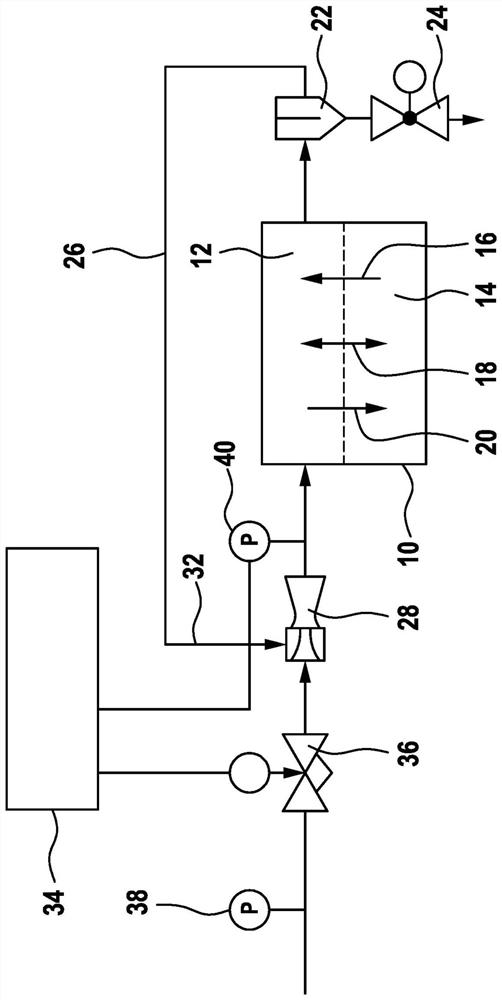
[0028] figure 1 A diagram showing components of a fuel cell system with a dosing valve, an injection pump, a fuel cell, and a controller.

[0029] by figure 1 The diagram shown in FIG. 1 shows that a fuel cell system 10 , one of which is illustrated here as an example of a fuel cell, includes an anode-side path 12 and a cathode-side path 14 . Within the fuel cell system 10, N from the ambient air from the cathode side path 14 to the anode side path 12 occurs. 2 Diffusion16. Water exchange 18 occurs between the anode-side path 12 and the cathode-side path 14, and in addition H from the anode-side path 12 into the cathode-side path 14 2 Diffusion 20.

[0030] On the outlet s...


PUM


Abstract

The invention relates to a method for switching off a fuel cell system (10), comprising a jet pump (28) for feeding a gas flow on the anode side into a recirculation path (26), the jet pump (28) comprising a metering valve (36) for metering H2. During cooling of the fuel cell system (10), the nozzle (46) is driven in a pulsating through-flow manner at least once in order to discharge condensed water. The invention further relates to a jet pump (28) having a metering valve (36) and to the use of a method for switching off a fuel cell system (10).

Description

technical field [0001] The invention relates to a method for actuating a metering valve as part of an injection pump in a fuel cell system and to a metering valve as part of an injection pump. Background technique [0002] DE 10 2011 114 797 A1 relates to a method for operating a fuel cell system. At least one fuel cell is provided having an anode compartment and a cathode compartment, wherein fuel from a fuel source (H 2 ) is supplied to the anode chamber and unconsumed exhaust gas from the anode chamber is recirculated into the fuel flowing to the anode chamber by a gas jet pump, and the gas jet pump includes a heatable nozzle. The nozzles of the gas jet pump are heated only when no fuel is flowing through the gas jet pump. [0003] WO 2013 045 048 A1 relates to a method for shutting down a fuel cell system. The anode recirculation device includes a gas jet pump for pumping anode exhaust gas, wherein the gas jet pump is driven by a flow of fuel gas flowing into the gas ...

Claims


Application Information

Patent Timeline
Patent Type & Authority Applications(China)
IPC IPC(8): H01M8/04082F04F5/48H01M8/04089H01M8/04746
CPCH01M8/04097H01M8/04201H01M8/04753F04F5/48H01M8/04303H01M8/04253H01M8/04179Y02E60/50F04B49/03F04D15/0005
Inventor H-C·马盖尔
Owner ROBERT BOSCH GMBH
Why Eureka
Try Eureka