Air suction connecting apparatus for closed rotary compressor

A rotary compressor and connecting device technology, applied in the field of compressor construction, can solve the problems of closed rotary compressors such as difficult operation, compression efficiency drop, thermal deformation, etc., to prevent pressure rise, improve performance, and reduce defects rate effect

Inactive Publication Date: 2008-02-27
LG ELECTRONICS (TIANJIN) APPLIANCES CO LTD
View PDF7 Cites 0 Cited by
  • Summary
  • Abstract
  • Description
  • Claims
  • Application Information

AI Technical Summary

Problems solved by technology

The surface of the cylinder 9 and the rolling piston 7 inside the hermetic rotary compressor is uneven due to the flame when welding the suction pipe 23, the inflow pipe 20, and the gas-liquid separator conduit 21, so that the hermetic rotary compressor is difficult to operate and Compression efficiency decreases and thermal deformation is induced

Method used


Image

  • Air suction connecting apparatus for closed rotary compressor
  • Air suction connecting apparatus for closed rotary compressor
  • Air suction connecting apparatus for closed rotary compressor

Examples


Embodiment Construction

[0025] The present invention will be described in detail below with reference to the figures and examples.

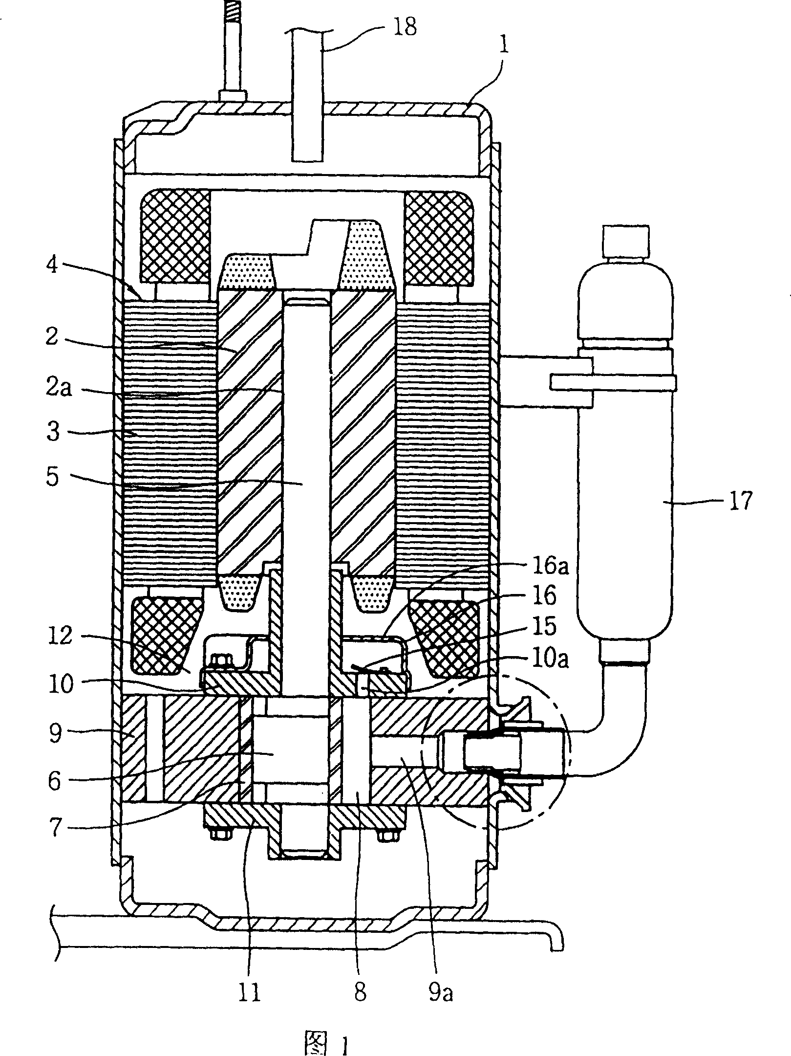
[0026] As shown in Figures 1 and 3, a motor 4 is installed inside the airtight container 1, and a crankshaft 5 is pressed and fixed in the center of the rotor 2, and a rolling piston 7 is inserted into the lower end and outside of the eccentric part 6 of the crankshaft 5 to form a cylinder. 9. A compression space 8 where the inner rolling piston 7 compresses the refrigerant gas, and a compression mechanism 12 composed of upper and lower bearings 10 and 11.

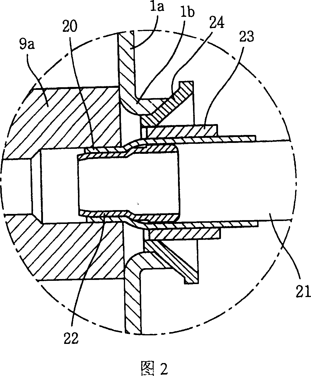
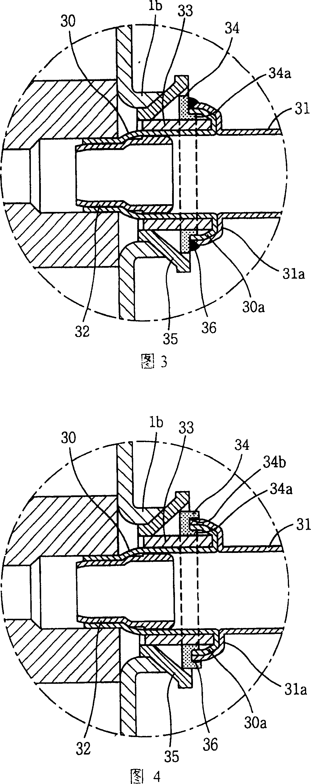
[0027] A gas-liquid separator 17 is provided on the side of the suction port 9a of the cylinder 9 to prevent the inflow of liquid refrigerant, and a discharge pipe 18 is provided on the top of the sealed container 1 to discharge the high-pressure refrigerant gas compressed by the compression mechanism 12 to the outside.

[0028] In such a hermetic rotary compressor, the gas suction connection device according to the...


PUM


Abstract

The present invention discloses gas sucking pipe connecting unit of sealed rotary compressor, and belongs to the field of compressor structure. The present invention includes pressing annular inlet pipe into the inlet of the cylinder, pressing the outside of the inlet pipe into outside of the sucking pipe and welding the inside of the canal of liquid storage to the outside of the inlet pipe. The present invention can prevent the surface of the cylinder and the rotor inside the compressor from becoming uneven during the welding and ensure the smooth running of the compressor. Said method can minimize the thermal deformation during welding. Therefore, the present invention can raise the performance and quality of sealed rotary compressor.

Description

technical field [0001] The present invention relates to the construction of compressors, in particular to gas suction connections for hermetic rotary compressors. Background technique [0002] In the existing fully enclosed compressor, as shown in Figure 1, a motor 4 composed of a rotor 2 and a stator 3 is arranged inside a sealed container 1, and a crankshaft 5 is pressed and fixed in a shaft hole 2a formed in the center of the rotor 2 in a vertical direction. . [0003] A compression mechanism 12 is provided at the lower end of the crankshaft 5 . And the compression mechanism is integrated with 6. The outer side of the eccentric part 6 is inserted into the rolling piston 7 . And the compression mechanism forms the rolling piston 7 to operate, and the compression space 8 for compressing the refrigerant gas is formed by the cylinder 9 and the upper and lower bearings 10,11. [0004] A valve plate 15 is provided on the outlet side of the discharge hole 10a on the upper be...

Claims


Application Information

Patent Timeline
Patent Type & Authority Patents(China)
IPC IPC(8): F04C29/00
Inventor 卞相明
Owner LG ELECTRONICS (TIANJIN) APPLIANCES CO LTD
Why Eureka
Try Eureka