
Intelligent automatic threading numerical control linear cutting machine tool

A wire cutting machine tool and automatic threading technology, which is applied in electric processing equipment, metal processing equipment, manufacturing tools, etc., can solve the problems of time-consuming, laborious, dirty and not environmentally friendly, and increased labor costs, so as to avoid excessive wire withdrawal and reduce production The effect of cost and threading process stability

Pending Publication Date: 2022-04-26
朱双全
View PDF0 Cites 1 Cited by
  • Summary
  • Abstract
  • Description
  • Claims
  • Application Information

AI Technical Summary

Problems solved by technology

When threading the wire, the cutting fluid on the workbench often drips on the hands and clothes, making it dirty and not environmentally friendly, and because the diameter of the threading wire is small, manual threading is difficult, time-consuming and laborious, and the work efficiency is slow
[0003] With the development of the times and the increase of labor costs, the pain point of slow work efficiency caused by manual wire threading has become more prominent. After years of experience and research experiments, the inventor invented an intelligent automatic wire threading CNC wire cutting machine tool

Method used


Image

  • Intelligent automatic threading numerical control linear cutting machine tool
  • Intelligent automatic threading numerical control linear cutting machine tool
  • Intelligent automatic threading numerical control linear cutting machine tool

Examples


Embodiment Construction

[0027] The following will clearly and completely describe the technical solutions in the embodiments of the present invention with reference to the accompanying drawings in the embodiments of the present invention. Obviously, the described embodiments are only some, not all, embodiments of the present invention. Based on the embodiments of the present invention, all other embodiments obtained by persons of ordinary skill in the art without making creative efforts belong to the protection scope of the present invention.

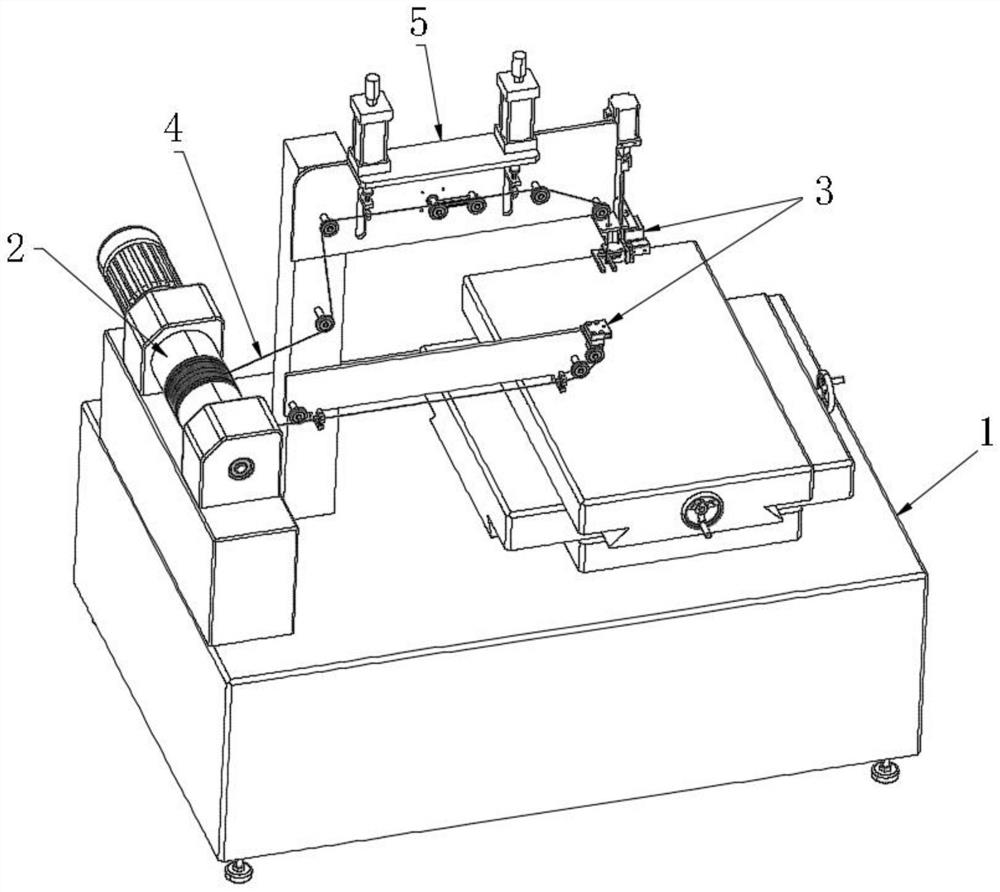
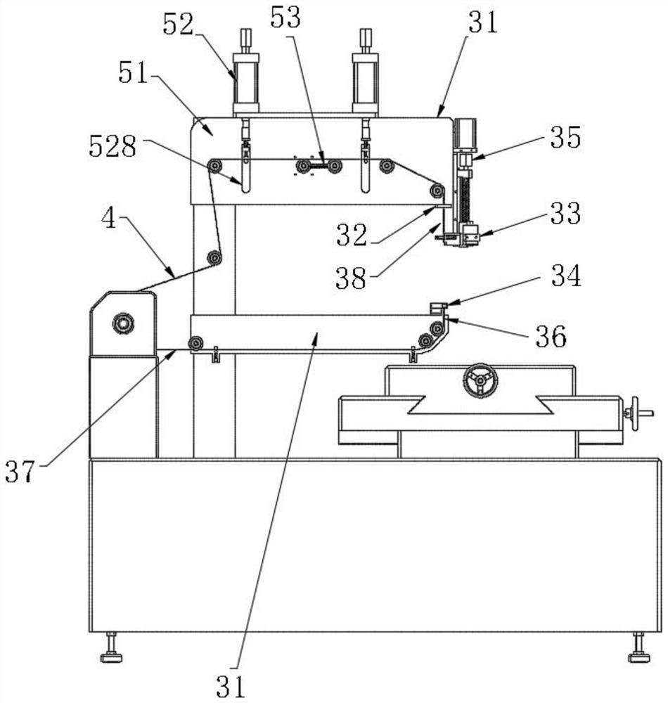
[0028] see Figure 1-6, intelligent automatic threading CNC wire cutting machine tool, including machine tool 1, machine tool 1 is provided with loop wire drum 2, wire pressing mechanism 5 and wire threading mechanism 3. An electrode wire 4 is wound on the loop wire drum 2 . The wire pressing mechanism 5 is used for tensioning the electrode wire 4 . The wire threading mechanism 3 includes a lower wire frame 31 installed on the machine tool 1, and the lower w...


PUM


Abstract

The invention discloses an intelligent automatic wire penetrating numerical control wire cutting machine tool, and relates to the technical field of wire cutting machine tools, the intelligent automatic wire penetrating numerical control wire cutting machine tool comprises a machine tool body, the machine tool body is provided with a wire winding cylinder, a wire pressing mechanism and a wire penetrating mechanism, an electrode wire is wound on the wire winding cylinder, and the wire penetrating mechanism comprises a lower wire frame, a limiting plate, a wire clamping moving chuck, a limiting frame, a first moving device, a wire connector, a needle leading wire and a connecting part. A water nozzle penetrates through the limiting plate, a needle leading wire is clamped through the wire clamping moving chuck, then the wire clamping moving chuck is driven through the first moving device, the needle leading wire can move towards the limiting frame and is finally clamped by the wire connector, and therefore a wire conveying closed loop is formed by the electrode wire, the wire connector, the connecting part and the wire winding barrel. When the needle guide wire is driven to the limiting frame by the wire clamping moving chuck and the first moving device, the needle guide wire correspondingly passes through a hole site in a workpiece, automatic wire threading of the workpiece is achieved, the problems encountered by manual wire threading are effectively avoided, the labor cost is effectively reduced, and the working efficiency is improved.

Description

technical field [0001] The invention relates to the technical field of wire-cutting machine tools, in particular to an intelligent automatic wire-threading numerical control wire-cutting machine tool and a fast wire-cutting machine tool. Background technique [0002] The wire electric discharge machine tool uses molybdenum wire or hard brass wire as the electrode wire. Under the action of high-frequency pulse voltage, the liquid medium is broken down to form an electric spark discharge, and at the same time, heat is generated to partially melt the metal on the surface of the workpiece (also It is called electrocorrosion), and at the same time, the cutting fluid flushes the cutting part, and controls the movement of the electrode wire through the controller to form a preset shape and size on the workpiece. The wire threading of traditional wire-cutting machine tools mostly adopts manual threading. The wire loading, wire-drawing and wire-threading process of traditional wire-c...

Claims


Application Information

Patent Timeline
Patent Type & Authority Applications(China)
IPC IPC(8): B23H7/02B23H11/00
CPCB23H7/02B23H11/00
Inventor 朱双全
Owner 朱双全
Learn More