
Method for manufacturing complete implant dental bridge

A manufacturing method and dental implant technology, applied in the field of oral cavity, can solve problems such as increased labor costs and material costs, poor occlusion, inaccurate occlusal records, etc., to achieve material and labor cost control, accurate occlusion and placement, and improve satisfaction degree of effect

Pending Publication Date: 2022-04-15
东莞定远陶齿制品有限公司
View PDF0 Cites 0 Cited by
  • Summary
  • Abstract
  • Description
  • Claims
  • Application Information

AI Technical Summary

Problems solved by technology

Before the improvement of full-mouth implant bridge: After taking the model and wax embankment, the doctor will directly cast the occlusal and follow-up permanent crown restoration. Because the doctor’s technique of taking the model and wax embankment is uneven, the doctor’s occlusal record is usually inaccurate after taking the model. After the good occlusion according to the occlusal record of the processing institute, there is too much difference from the occlusion in the mouth, and when the doctor transfers the rod to take the model, usually the transfer rod is not inserted in place, resulting in the denture being made either cannot be in place, or the occlusion is poor, and even some models are due to poor occlusion Bad metal design leads to rework and rework, and some model patients are not in place when they try them on, and they can’t wear them, so the rate of rework and repair is high, which seriously affects the relationship between doctors and patients and the reputation of the production company, and also causes labor costs and material costs. improve

Method used


Image

  • Method for manufacturing complete implant dental bridge
  • Method for manufacturing complete implant dental bridge
  • Method for manufacturing complete implant dental bridge

Examples


Embodiment 1

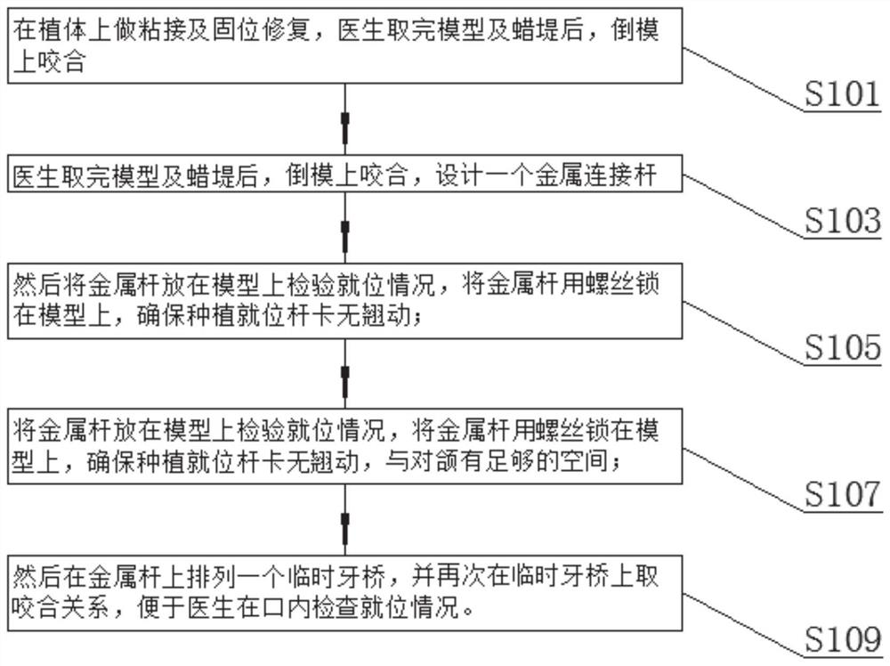
[0032] like Figure 1-6 As shown, the method for making a full-mouth implant bridge according to an embodiment of the present invention includes the following steps;

[0033] Do bonding and retention repair on the implant, after the doctor has taken the model and wax embankment, the mold will be occluded;

[0034] After the doctor took the model and the wax embankment, he reversed the model and occluded it, and designed a metal connecting rod;

[0035] Then put the metal rod on the model to check the in-position situation, and lock the metal rod on the model with screws to ensure that the planting in place bar card does not warp;

[0036] Put the metal rod on the model to check the in-position situation, and lock the metal rod on the model with screws to ensure that the implant is in place without warping and there is enough space with the opposing jaw;

[0037] Then arrange a temporary bridge on the metal rod, and take the occlusal relationship on the temporary bridge again...

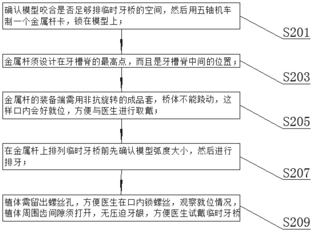
Embodiment 2

[0039] like Figure 1-6 As shown, before making the metal rod, the following steps are also included;

[0040] Confirm whether the occlusion of the model is enough to accommodate the temporary bridge, and then use a five-axis locomotive to make a metal bar and lock it on the model;

[0041] The metal rod must be designed at the highest point of the alveolar ridge and in the middle of the alveolar ridge;

[0042] The equipment end of the metal rod needs to use a non-rotation-resistant finished sleeve, and the bridge body cannot be tilted, so that the mouth will be in place, and it is convenient to take and wear with the doctor;

[0043] Before arranging the temporary bridge on the metal rod, first confirm the radian size of the model, and then arrange the teeth;

[0044] Screw holes should be reserved for the implant, so that the doctor can lock the screw in the mouth and observe the position. The gap between the teeth around the implant must be opened so that there is no pre...

Embodiment 3

[0046] like Figure 1-6 As shown, the metal bar is 3mm high, 2mm wide and 2-3mm space is reserved for the gums. The upper jaw of the row of teeth usually has (T1, T3, T6, TL1), and the lower jaw has (5L, 8L). The size of the row of teeth is arranged, and the occlusal relationship is taken on the temporary dental bridge, and the occlusal, length, radian, size and length in the mouth can be checked on the temporary dental bridge.

[0047] like figure 1 As shown, according to the embodiment of the present invention, a method for making a full-mouth implant bridge is also provided.

[0048] Include the following steps:

[0049] S101. Perform bonding and retention repair on the implant. After the doctor takes the model and wax embankment, the model is reversed and occluded;

[0050] S103. After the doctor takes the model and the wax embankment, he inverts the model and occludes it, and designs a metal connecting rod;

[0051] S105, then put the metal rod on the model to check t...


PUM


Abstract

The invention discloses a manufacturing method of a complete implant dental bridge. Carrying out bonding and retention repair on the implant, and after a doctor takes the model and the wax rim, carrying out reverse mold occlusion; after a doctor takes the model and the wax embankment, meshing on the reverse mold, and designing a metal connecting rod; then the metal rod is placed on the model, the in-place condition is checked, the metal rod is locked on the model through a screw, and it is ensured that the in-place planting rod clamp does not tilt; a metal rod is placed on the model to detect the in-position condition, the metal rod is locked on the model through a screw, it is guaranteed that the in-position planting rod clamp does not tilt, and enough space is provided for the jaw; and then a temporary tooth bridge is arranged on the metal rod, and the occlusion relationship is taken on the temporary tooth bridge again, so that a doctor can conveniently examine the in-position condition in the mouth. The model has the beneficial effects that the occlusion and the insertion path of the half-mouth dental model and the full-mouth dental model transferred from the inside of the mouth by a doctor to the model are more accurate, the rework rate and the doctor seeing rate of a patient are reduced, the material and labor cost is controlled, and the satisfaction degree of customers is further improved.

Description

technical field [0001] The invention relates to the field of oral cavity technology, in particular to a method for making a full-mouth implant bridge. Background technique [0002] Dental implants are usually implanted in the mouth, usually 4-6 implants are implanted in the half mouth, and bonding and retention are performed on the implants. Before the improvement of full-mouth implant bridge: After taking the model and wax embankment, the doctor will directly cast the occlusal and follow-up permanent crown restoration. Because the doctor’s technique of taking the model and wax embankment is uneven, the doctor’s occlusal record is usually inaccurate after taking the model. After the good occlusion according to the occlusal record of the processing institute, there is too much difference from the occlusion in the mouth, and when the doctor transfers the rod to take the model, usually the transfer rod is not inserted in place, resulting in the denture being made either cannot ...

Claims


Application Information

Patent Timeline
IPC IPC(8): A61C8/00
Inventor 陈超杰
Owner 东莞定远陶齿制品有限公司
Learn More