A kind of high-resolution oct imaging device and imaging method thereof
An imaging device and high-resolution technology, applied in the field of optical imaging, can solve problems such as single measurement performance, small imaging field of view, and slow acquisition speed, and achieve the effects of improving sensitivity, high recovery efficiency, and improving receiving efficiency
- Summary
- Abstract
- Description
- Claims
- Application Information
AI Technical Summary
Problems solved by technology
Method used
Image

Examples
Embodiment 1
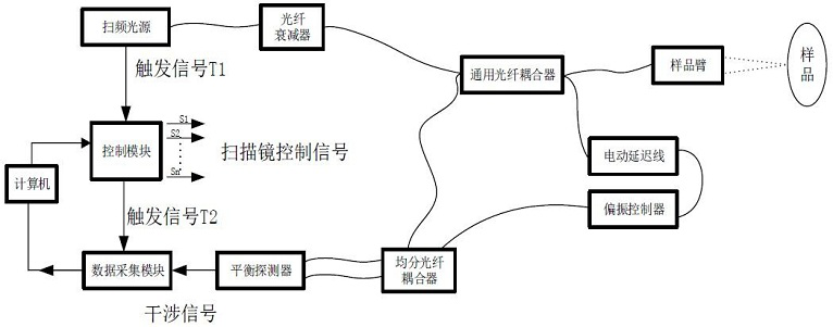
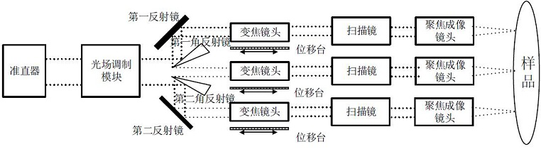
[0053] Such as figure 2 As shown, in this embodiment, the sample is the outer skin, cerebral cortex, or cornea, etc., and there is no lens-like medium between the sample to be imaged and the imaging lens, so the imaging lens adopts a focusing imaging lens. In this embodiment, the first and second corner reflectors are used to divide a non-diffraction beam output by the light field modulation module into three non-diffraction beams, and the optical transmission path is changed by the first and second reflectors, respectively transmitting To the first to third sample arm branches; according to the interference signals of each sample arm branch, splicing and forming OCT images with high resolution and large field of view. The beam irradiated on the sample by the three-way sample arm branch is reflected by the sample, returns to each sample arm branch, and finally returns to the collimator. The efficiency is theoretically 100% when the device loss is ignored.
Embodiment 2
[0055] Such as Figure 4 As shown, in this embodiment, the sample is the eye, and the first and second corner reflectors are used to divide a non-diffracting beam output by the light field modulation module into three non-diffracting beams, and the first and second reflectors The mirror changes the transmission path of the optical path and transmits them to the first to third sample arm branches respectively; among the three sample arm branches, the first and third sample arm branches are the optical path of the posterior segment of the eye, and the second sample arm branch is the front Light-section path; when imaging the posterior segment of the eye, there is a lens-like medium between the sample and the imaging lens, so the imaging lens of the optical path of the posterior segment of the eye uses a 4F imaging lens. When imaging the anterior segment, there is no similarity between the sample and the imaging lens. The medium of the lens function, so the imaging lens of the an...
Embodiment 3
[0058] Such as Image 6 As shown, in this embodiment, the sample is the outer skin, cerebral cortex, or cornea, etc., and there is no lens-like medium between the sample to be imaged and the imaging lens, so the imaging lens adopts a focusing imaging lens. In this embodiment, a polarization beam splitter and a third angle reflector are used to divide the light beam into three, and the light field adjustment mode includes the first and second light field adjustment modes; the Gaussian beam emitted from the collimator to the polarization splitter The polarizing beam splitter is divided into two parts by the polarizing beam splitter, the P polarized light is transmitted, and the S polarized light is reflected; the reflected S polarized light passes through the third mirror and the second half-wave plate in turn, and after passing through the second light field adjustment module, the Gaussian The light beam becomes a non-diffracting beam, and then the non-diffracting beam is sent ...
PUM
 Abstract
Description
Claims
Application Information
 - R&D
- Intellectual Property
- Life Sciences
- Materials
- Tech Scout
- Unparalleled Data Quality
- Higher Quality Content
- 60% Fewer Hallucinations
Browse by: Latest US Patents, China's latest patents, Technical Efficacy Thesaurus, Application Domain, Technology Topic, Popular Technical Reports.
© 2025 PatSnap. All rights reserved.Legal|Privacy policy|Modern Slavery Act Transparency Statement|Sitemap|About US| Contact US: help@patsnap.com