Eureka AIR delivers breakthrough ideas for toughest innovation challenges, trusted by R&D personnel around the world.

Flue gas waste heat utilization and carbon dioxide capture and recovery process

A carbon dioxide and flue gas waste heat technology, applied in indirect heat exchangers, lighting and heating equipment, chemical instruments and methods, etc., can solve problems such as unfavorable carbon dioxide adsorption, high energy consumption, and high requirements for flue gas components, and increase heat utilization High efficiency, energy saving and environmental protection double benefit effect

Pending Publication Date: 2022-04-05
YANTAI UNIV
View PDF0 Cites 0 Cited by
  • Summary
  • Abstract
  • Description
  • Claims
  • Application Information

AI Technical Summary

Problems solved by technology

Variable temperature operation requires periodic heating and cooling, which will not only reduce the service life of the solid adsorbent, but also increase the investment cost of the equipment and lead to high energy consumption
The physical pressure swing adsorption method can obtain a high volume fraction of product gas, but the adsorption capacity and adsorption rate of the adsorbent will decrease as the concentration of the adsorbed gas decreases, which is not conducive to the adsorption of low-concentration carbon dioxide.
Membrane separation technology realizes the separation and purification of carbon dioxide gas by using the different permeability of carbon dioxide and other gases through specific membranes. Although the membrane separation method is simple in process and convenient in operation, it has high requirements for flue gas components, and the membrane separation efficiency depends on the membrane separation efficiency. Permeability and selectivity, obtaining high capture rate and high volume fraction of product gas requires a multi-stage process, and the use of membrane separation alone to capture low-concentration carbon dioxide is costly and energy-intensive

Method used


Image

  • Flue gas waste heat utilization and carbon dioxide capture and recovery process

Examples


Embodiment Construction

[0024] The following will clearly and completely describe the technical solutions in the embodiments of the present invention with reference to the accompanying drawings in the embodiments of the present invention. Obviously, the described embodiments are only some of the embodiments of the present invention, not all of them. Based on the embodiments of the present invention, all other embodiments obtained by persons of ordinary skill in the art without making creative efforts belong to the protection scope of the present invention.

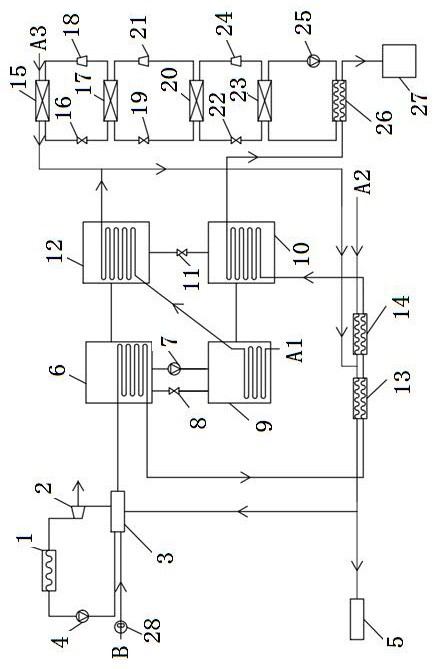
[0025] Such as figure 1As shown, a flue gas waste heat utilization and carbon dioxide capture and recovery system includes three parts: a steam power generation system, an absorption unit and a cascade refrigeration system.

[0026] The steam power generation system mainly includes a condenser 1, a steam turbine 2, a waste heat boiler 3, and a first circulation pump 4. Water inlet of boiler 3.

[0027] The absorption unit mainly includes a gene...


PUM


Abstract

The invention discloses a flue gas waste heat utilization and carbon dioxide capture and recovery process, an adopted system comprises a steam power generation system, an absorption type unit, a cascade refrigeration system and the like, high-temperature flue gas transfers heat to the steam power generation system through heat exchange, and the temperature of water in a waste heat boiler of the steam power generation system is increased. Flue gas serves as a heating medium to provide heat for the absorption unit, the flue gas exchanges heat with an evaporator of the absorption unit, the evaporation temperature of the absorption unit is increased, and the circulation efficiency is improved. And heat is transferred to a boiler or a power generation system through a condenser of the absorption type unit to supply water, and flue gas heat is recycled. And the cascade refrigeration system performs low-temperature liquefaction, so that the flue gas is liquefied under the condition of extremely low temperature, and the purpose of removing carbon dioxide is achieved. Flue gas heat is recycled repeatedly, the flue gas heat utilization rate is greatly increased, and energy-saving and environment-friendly double benefits are achieved.

Description

technical field [0001] The invention relates to a flue gas waste heat utilization and carbon dioxide capture and recovery process, belonging to the technical field of flue gas treatment. Background technique [0002] Global warming has brought extensive impacts on human social survival, economic and social development, and is one of the most severe and complex challenges faced by mankind in the 21st century. The main cause of global warming is the massive emissions of greenhouse gases such as carbon dioxide . On the one hand, it is to reduce carbon emissions from sources such as industry, transportation, and construction; on the other hand, the carbon emissions generated in manufacturing and life cannot be completely zeroed out, and relevant technologies need to be used to absorb and fix the emitted carbon dioxide and other greenhouse gases , Utilize it, separate the released carbon dioxide and other greenhouse gases from sources such as industrial exhaust, and carry out lo...

Claims


Application Information

Patent Timeline
IPC IPC(8): F28D21/00B01D53/00F01K11/02
Inventor 赵海波吴坤张静峰
Owner YANTAI UNIV
Why Eureka
Eureka Blog
Learn More