
LED packaging equipment

A technology of LED packaging and equipment, applied in the direction of electrical components, semiconductor/solid-state device manufacturing, circuits, etc., can solve the problems of reducing processing efficiency, reducing packaging quality, affecting dispensing accuracy, etc., to improve processing efficiency, improve stability, The effect of improving package quality

Pending Publication Date: 2022-04-01
深圳市伟方成科技有限公司
View PDF0 Cites 0 Cited by
  • Summary
  • Abstract
  • Description
  • Claims
  • Application Information

AI Technical Summary

Problems solved by technology

[0004] Existing LED packaging equipment usually uses three-axis linkage to drive the dispensing gun to move in space, which can accurately dispensing and packaging the points on the LED board, but there is no structure for clamping and positioning the LED board. Sometimes the LED board will slide, which affects the dispensing accuracy and reduces the packaging quality. Moreover, the existing LED packaging equipment cannot dispensing and loading and unloading the LED board at the same time. When an LED board is packaged, it needs to be manually processed. Loading and unloading, thus prolonging the downtime of the equipment and reducing the processing efficiency

Method used


Image

  • LED packaging equipment
  • LED packaging equipment
  • LED packaging equipment

Examples


Embodiment Construction

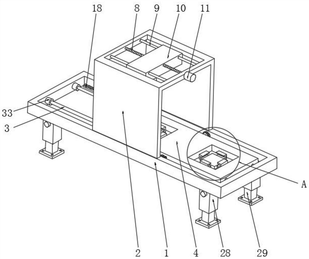
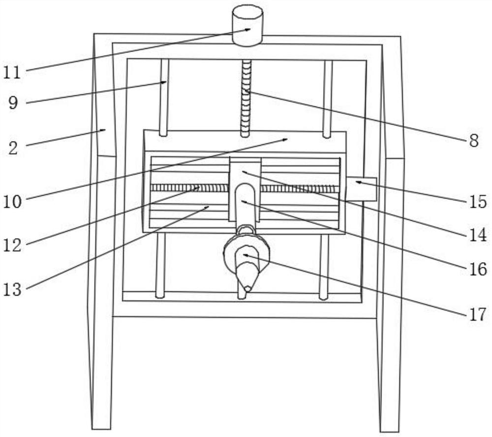
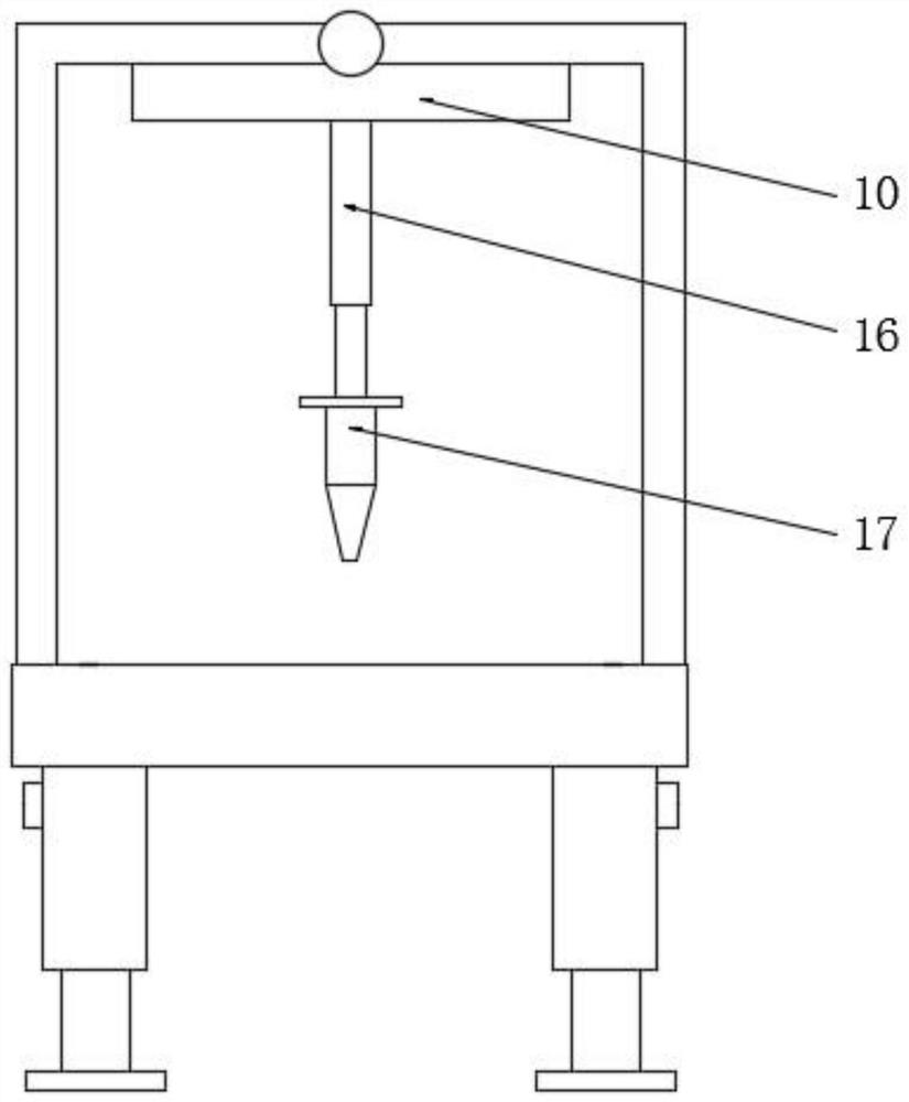
[0027] see Figure 1-7 , in an embodiment of the present invention, an LED packaging device includes a platen 1, a door frame 2 is fixed on the upper side of the platen 1 at the middle position, and a chute is opened on the upper side of the platen 1, and the inner side of the chute Two slide guide rods 3 parallel to each other are fixed, and the inner side of the chute is slidably connected with a station slide 4. There are two work slots at both ends, and the inside of the two work slots are provided with a workpiece supporting plate 5, and the inside of the two workpiece supporting plates 5 are equipped with a workpiece pressing mechanism, and the inside of the door frame 2 is located at the upper end position. Slidingly connected with a horizontal slide 10, the inside of the horizontal slide 10 is located in the middle position and is connected with a horizontal screw 8 through the rotation of the thread teeth. There are two transverse guide rods 9 slidingly connected at ...


PUM


Abstract

The invention relates to the technical field of dispensing packaging, in particular to LED packaging equipment, which is characterized in that a door frame is fixed at the middle section position of the upper side of a table plate, a sliding groove is formed in the upper side of the table plate, two parallel sliding plate guide rods are fixed on the inner side of the sliding groove, and a station sliding plate is slidably connected to the inner side of the sliding groove; the two sliding plate guide rods penetrate through and are slidably connected into a station sliding plate, two station grooves are formed in the two ends of the upper side of the station sliding plate, and workpiece supporting plates are arranged on the inner sides of the two station grooves. According to the invention, through the sliding plate movement driving mechanism, the station sliding plate can be driven to slide on the inner side of the sliding groove, so that the positions of the two station grooves above the station sliding plate are mutually converted, and when an LED plate in one station groove is subjected to dispensing packaging, the LED plate in the other station groove can be subjected to feeding and discharging; and dispensing and loading and unloading can be simultaneously carried out on the LED plate under the condition of no shutdown, so that the processing efficiency of dispensing and packaging is greatly improved.

Description

technical field [0001] The invention relates to the technical field of glue dispensing packaging, in particular to LED packaging equipment. Background technique [0002] LED (semiconductor light-emitting diode) package refers to the package of light-emitting chips. The function of the package is to provide sufficient protection for the chip to prevent the chip from failing due to long-term exposure in the air or mechanical damage, so as to improve the stability of the chip; for LED packages, it is also required With good light extraction efficiency and good heat dissipation, good packaging can make LEDs have better luminous efficiency and heat dissipation environment, thereby improving the life of LEDs. [0003] LED packaging usually adopts the method of dispensing glue. When dispensing glue, the LED board is fixed first, and then the dispensing gun is controlled to move above the LED board, and the points on the LED board are dispensing and packaged. [0004] Existing LED ...

Claims


Application Information

Patent Timeline
IPC IPC(8): H01L21/67H01L21/687H01L33/48
Inventor 王伟吴国庆尹建平
Owner 深圳市伟方成科技有限公司
Learn More