Gas diffusion layer for improving water management capability of fuel cell and preparation method of gas diffusion layer

A gas diffusion layer and fuel cell water technology, which is applied to fuel cell parts, fuel cells, electrical components, etc., can solve the problems of moisturizing, drainage effect reduction, no consideration of cathode and anode, and inability to moisturize, etc., to achieve improvement Effects of water management ability, improvement of output performance, and improvement of reaction efficiency

Pending Publication Date: 2022-03-25
SHANXI INST OF COAL CHEM CHINESE ACAD OF SCI
View PDF3 Cites 2 Cited by
  • Summary
  • Abstract
  • Description
  • Claims
  • Application Information

AI Technical Summary

Problems solved by technology

Antonacci P et al. (document Balancing mass transport resistance and membrane resistance when tailoring microporous layer thickness for polymer electrolyte membrane fuel cells operating at high current densities. ElectrochimicaActa, 2016,188:888-897) adjusted the thickness of the microporous layer and found that the thickness of the microporous layer was The drainage performance is the best under the condition of high current density at 50 microns, without considering the influence of the pore size of the microporous layer
CN111146467A discloses a preparation method of a microporous layer gas diffusion layer with gradient pore size. Different kinds of carbon powder, absolute alcohol and hydrophobic agent are used to form a slurry, and two layers of microporous layers with different pore sizes are coated on the support layer. , so that the pore size tends to increase from the catalyst layer to the support layer, which is conducive to the discharge of water under high humidity. However, this m...

Method used


Image

  • Gas diffusion layer for improving water management capability of fuel cell and preparation method of gas diffusion layer
  • Gas diffusion layer for improving water management capability of fuel cell and preparation method of gas diffusion layer
  • Gas diffusion layer for improving water management capability of fuel cell and preparation method of gas diffusion layer

Examples


Embodiment 1

[0032] A method for preparing a gas diffusion layer for improving the water management capability of a fuel cell, comprising the following steps:

[0033] Step 1: Select carbon nanotubes with a diameter of 30nm, and use an acid oxidation method to oxidize the carbon nanotubes, and the oxygen-carbon ratio in the oxidized carbon nanotubes is 0.10;

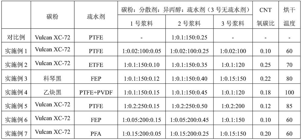
[0034] Step 2: Mix Vulcan XC-72, dispersant, isopropanol and PTFE according to the mass ratio of 1:0.02:100:0.05 and 1:0.02:100:0.25 respectively, and make a slurry evenly by stirring, ultrasonic and sand milling Material No. 1 and slurry No. 2; the oxidized carbon nanotubes, dispersant and isopropanol were mixed in a mass ratio of 1:0.02:100, and the slurry No. 3 was uniformly mixed by stirring, ultrasonication, and sand milling;

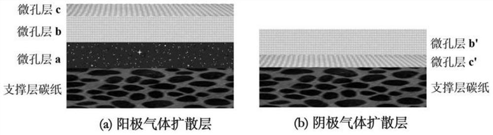
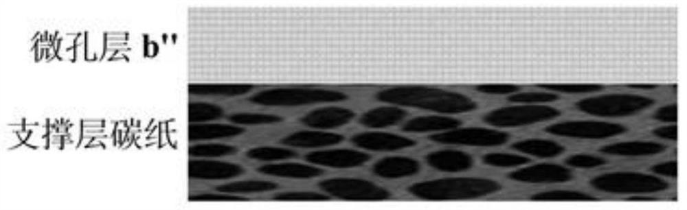
[0035] Step 3: Apply slurry No. 1 on the surface of the support layer carbon paper, dry at 60°C to form microporous layer a, apply slurry No. 2 on the surface of microporous layer a, and dry at 60°C to fo...

Embodiment 2

[0039] A method for preparing a gas diffusion layer for improving the water management capability of a fuel cell, comprising the following steps:

[0040] Step 1: Select carbon nanotubes with a diameter of 50nm, and use an electrochemical oxidation method to oxidize the carbon nanotubes. The oxygen-to-carbon ratio in the oxidized carbon nanotubes is 0.25;

[0041] Step 2: Mix Vulcan XC-72, dispersant, isopropanol and ETFE according to the mass ratio of 1:0.1:150:0.10 and 1:0.1:150:0.35 respectively, and make a slurry evenly by stirring, ultrasonic and sand milling Material No. 1 and slurry No. 2; the oxidized carbon nanotubes, dispersant and isopropanol were mixed in a mass ratio of 1:0.1:120, and the slurry No. 3 was uniformly mixed by stirring, ultrasonication, and sand milling;

[0042] Step 3: Apply slurry No. 1 on the surface of the support layer carbon paper, dry at 70°C to form microporous layer a, apply slurry No. 2 on the surface of microporous layer a, and dry at 70°...

Embodiment 3

[0046] A method for preparing a gas diffusion layer for improving the water management capability of a fuel cell, comprising the following steps:

[0047] Step 1: Select carbon nanotubes with a diameter of 100nm, and use an electrochemical oxidation method to oxidize the carbon nanotubes. The oxygen-to-carbon ratio in the oxidized carbon nanotubes is 0.22;

[0048] Step 2: Mix Ketjen Black, dispersant, isopropanol and FEP according to the mass ratio of 1:0.1:150:0.12 and 1:0.1:150:0.40, respectively, and make a slurry evenly by stirring, ultrasonic and sand milling No. 1 and No. 2 slurry; the oxidized carbon nanotubes, dispersant and isopropanol are mixed according to the mass ratio of 1:0.15:150, and the slurry No. 3 is uniformly mixed by stirring, ultrasonic and sand milling;

[0049] Step 3: Apply slurry No. 1 on the surface of the support layer carbon paper, dry at 80°C to form microporous layer a, apply slurry No. 2 on the surface of microporous layer a, and dry at 80°C t...


PUM

PropertyMeasurementUnit
Diameteraaaaaaaaaa
Surface contact angleaaaaaaaaaa

Abstract

The invention belongs to the technical field of fuel cells, and particularly relates to a gas diffusion layer for improving the water management capability of a fuel cell and a preparation method thereof. Differential gradient structure design is carried out on the microporous layer of the cathode/anode gas diffusion layer, the cathode is designed to be of a double-layer gradient structure, the anode is of a three-layer gradient structure, the purposes of moisturizing under the low-humidity condition and draining under the high-humidity condition in the working state of the fuel cell are achieved, the reaction efficiency in the reaction process of the fuel cell is better improved, and the service life of the fuel cell is prolonged. The water management capability of the fuel cell is greatly improved, so that the output performance of the fuel cell is improved. In addition, the operation process is simple, only slurry preparation, coating, drying and roasting are needed, and rare reagents and complex instruments and equipment are not needed.

Description

technical field [0001] The invention belongs to the technical field of fuel cells, and in particular relates to a gas diffusion layer for improving the water management capability of fuel cells and a preparation method thereof. Background technique [0002] Hydrogen energy is an ideal clean energy. Hydrogen fuel cell vehicles have the advantages of fast filling speed, good low-temperature performance, and long cruising range. It is an important direction for future automobiles to be electrified and low-carbon. Low-carbon transportation has far-reaching significance. Among them, the proton exchange membrane fuel cell (PEMFC) has been widely researched and popularized due to its advantages of high power density and fast start-up speed. During the reaction process of PEMFC, the proton exchange membrane needs to be fully wetted, because the protons generated in the anode catalyst layer are hydrated protons (H 3 o + ) in the form of transmission. In the absence of water, the ...

Claims


Application Information

Patent Timeline
IPC IPC(8): H01M8/02H01M8/0245
CPCH01M8/0245H01M8/02
Inventor 吴刚平刘玉婷
Owner SHANXI INST OF COAL CHEM CHINESE ACAD OF SCI
Why Eureka
Try Eureka