Wet chemical treatment equipment for printed circuit board
A board wet chemistry and printed circuit technology, which is applied in the field of printed circuit board processing, can solve the problems that the processing liquid is inconvenient for uniform contact with the circuit board, inconvenient circulation operation, inconvenient rapid treatment of bubbles and effusion, etc., to reduce labor costs The effect of reducing the cost, reducing the time spent, and reducing the occupied area
- Summary
- Abstract
- Description
- Claims
- Application Information
AI Technical Summary
Problems solved by technology
Method used
Image

Examples
Embodiment 1
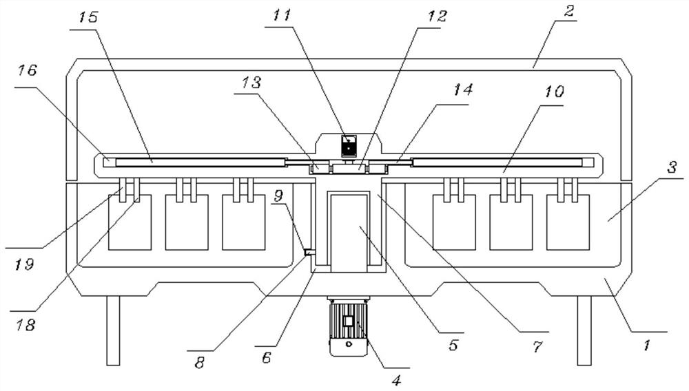
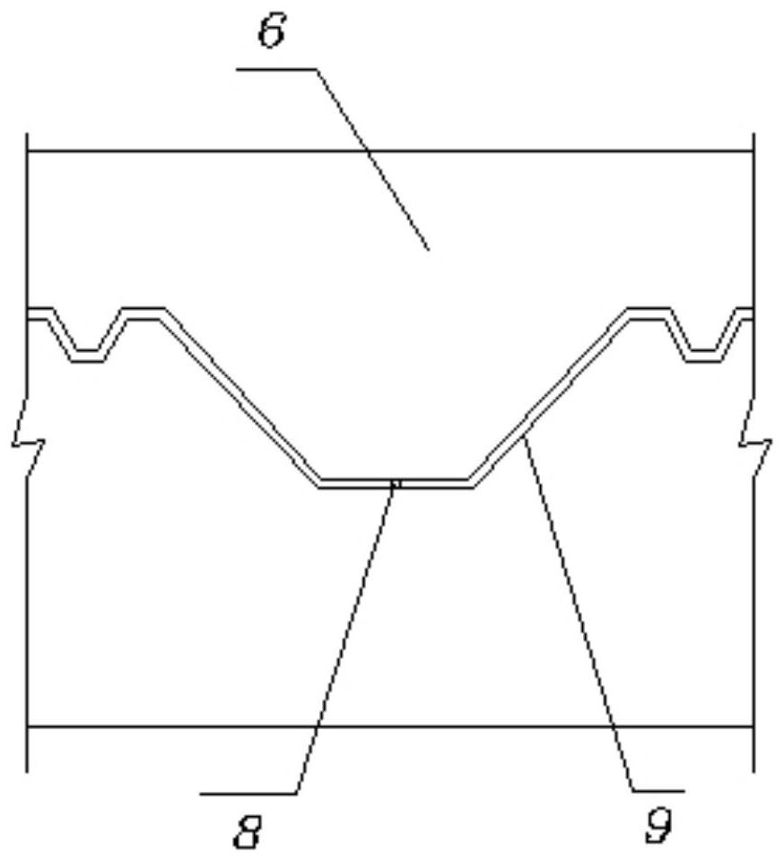
[0038] see Figure 1-3 , including a frame 1, a top cover 2 is installed on the top of the frame 1, and a processing chamber 3 is opened on the upper end surface of the frame 1, and a partition plate 301 is arranged between the processing chambers 3; it also includes: a first motor 4 , the first motor 4 is fixed on the bottom of the frame 1, and the output end of the first motor 4 is connected with a guide post 5, and the guide post 5 is located in the movable groove 6, and the movable groove 6 is opened in the middle part of the top of the frame 1, Guide column 5 is provided with movable column 7, and the outside of movable column 7 is fixed with guide bar 8, and guide bar 8 is positioned at guide groove 9, and guide groove 9 is offered on the inwall of movable groove 6, and the outer side of movable column 7 The top is located above the frame 1, and the side of the movable column 7 is fixed with a mounting plate 10, and the inside of the movable column 7 top is embedded with...
Embodiment 2
[0040] see Figure 1-2 , 4-6 and Figure 9 , the replacement slot 17, the replacement slot 17 is opened at the bottom of the mounting plate 10, and the first splint 18 and the second splint 19 with a "T" shape structure on the front are installed in the replacement slot 17, the first splint 18 and the second splint One end of clamping plate 19 is positioned at the below of mounting plate 10, and the inboard of first clamping plate 18 and the bottom of second clamping plate 19 are all connected with clip 21 by fixed spring 20, and the side of first clamping plate 18 and second clamping plate 19 and replacement The corresponding position of the inner wall of the slot 17 is fixed with a magnetic sheet 22, and the bottom edge of the mounting plate 10 is provided with an inner slot 23, and the inner slot 23 is fitted with a mounting strip 24 with a "T"-shaped structure on the front, and an adjusting plate 15 The bottom of the bottom is respectively fixed with a push rod 25 and a c...
Embodiment 3
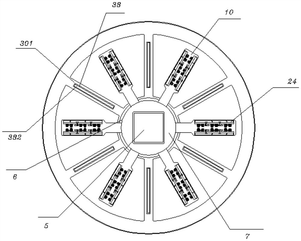
[0042] see Figure 1-3 with Figure 7-8, the collection tank 38, the collection tank 38 is opened on the top of the dividing plate 301, and the collection bucket 39 is fixed on the inner wall of the collection tank 38, and the bottom of the collection bucket 39 is connected with the air collection pipe 40, and one end of the air collection pipe 40 is connected through the There is a gas collecting ring 41, the top of the gas collecting ring 41 is connected to the output end of the second air pump 42, and the second air pump 42 is fixed at the bottom of the frame 1, and the collecting tank 38 is connected with a sealing plate 382 through a support spring 381 , and the bottom of the collecting tank 38 is fixed with a pressure sensor 383, and the top of the sealing plate 382 is located above the partition plate 301, the top of the sealing plate 382 is designed in an isosceles trapezoidal structure, and the sides of the sealing plate 382 top are in line with the collecting tank T...
PUM
 Abstract
Description
Claims
Application Information
 - R&D
- Intellectual Property
- Life Sciences
- Materials
- Tech Scout
- Unparalleled Data Quality
- Higher Quality Content
- 60% Fewer Hallucinations
Browse by: Latest US Patents, China's latest patents, Technical Efficacy Thesaurus, Application Domain, Technology Topic, Popular Technical Reports.
© 2025 PatSnap. All rights reserved.Legal|Privacy policy|Modern Slavery Act Transparency Statement|Sitemap|About US| Contact US: help@patsnap.com