
Millimeter wave array antenna with high gain and low sidelobe level characteristics

An array antenna and low sidelobe technology, applied in the field of millimeter wave array antenna, can solve the problems of low sidelobe, achieve good cross-polarization characteristics, improve radiation characteristics, and simplify the feeding network

Pending Publication Date: 2022-03-18
ARMY ENG UNIV OF PLA
View PDF0 Cites 1 Cited by
  • Summary
  • Abstract
  • Description
  • Claims
  • Application Information

AI Technical Summary

Problems solved by technology

Although different methods can be used to realize high-gain millimeter-wave antennas, it is necessary to reduce the loss caused by complex transmission lines and achieve low sidelobe characteristics, which puts forward strict requirements on antenna design

Method used


Image

  • Millimeter wave array antenna with high gain and low sidelobe level characteristics
  • Millimeter wave array antenna with high gain and low sidelobe level characteristics
  • Millimeter wave array antenna with high gain and low sidelobe level characteristics

Examples


Embodiment Construction

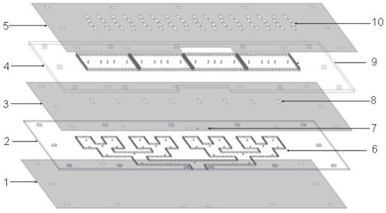
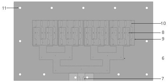
[0026] Such as figure 1 , figure 2 , image 3 As shown, a millimeter-wave array antenna based on high-gain and low-sidelobe level characteristics, upper and lower dielectric plates, GCPW feed structure, one-to-four power divider and four-element SIW-based resonant cavity TE 440 slotted leaky wave antenna array.

[0027] The present invention has a compact structure and consists of upper and lower dielectric plates. The upper and lower surfaces of the lower dielectric plate 2 cover the lower metal surface 3 and the metal ground 1 respectively, and the lower metal surface 3 is etched with four sets of periodically arranged coupling gap pairs 8 and a GCPW feed structure 7, the one-to-four power divider 6 is symmetrically placed on the lower dielectric plate 2, and a group of metallized through holes 11 are evenly etched along the dielectric plate; the quadruple is based on the SIW resonant cavity TE 440 The slot leaky wave antenna array of the mold is located on the upper die...


PUM


Abstract

The invention discloses a millimeter wave array antenna with high gain and low sidelobe level characteristics. The millimeter wave array antenna comprises a GCPW feed structure, a one-to-four power divider and a quaternary slot leaky-wave antenna array based on a SIW resonant cavity TE440 mode, a lower metal surface and a metal ground cover the upper surface and the lower surface along the length direction of the lower-layer dielectric plate respectively; four groups of periodically arranged coupling slot pairs and a GCPW feed structure are etched on the lower metal surface; the one-to-four power dividers are symmetrically arranged on the lower-layer dielectric plate, and a group of metalized through holes are uniformly etched along the periphery of the upper-layer dielectric plate; the four-element slot leaky-wave antenna array based on the SIW resonant cavity TE440 mode is located on the upper dielectric plate, and four groups of periodically arranged metalized through hole arrays are etched on the upper dielectric plate. According to the invention, the effective excitation of the planar antenna is realized by adopting GCPW side feeding, the feeding form is simple, the high gain characteristic with ultra-low sidelobe level is realized, and the antenna has potential application value in 5G mobile communication, satellite communication, millimeter wave communication and other systems in the future.

Description

technical field [0001] The invention relates to a slot leaky wave antenna, in particular to a millimeter wave array antenna with high gain and low side lobe level characteristics. Background technique [0002] Large system capacity, high data rate, low latency, and large-scale device connectivity are the performance goals of fifth-generation (5G) mobile communication technologies. Compared with the increasingly crowded sub-6GHz frequency band, the 5G millimeter wave (mmW) frequency band has more abundant spectrum resources and available areas. However, millimeter-wave antennas have disadvantages such as large transmission loss, small structural size, high processing precision, and high processing cost. [0003] In the design process of high-gain millimeter-wave antennas, generally speaking, the more the number of elements, the higher the gain, but the more complex the feeding network, the greater the transmission loss. If a "big" antenna unit can be used to replace the r...

Claims


Application Information

Patent Timeline
Patent Type & Authority Applications(China)
IPC IPC(8): H01Q21/06H01Q21/00H01Q1/24H01Q1/00
CPCH01Q21/064H01Q21/068H01Q21/0006H01Q1/241H01Q1/002
Inventor 马文宇曹文权张邦宁王闯李丹华
Owner ARMY ENG UNIV OF PLA
Learn More