Equipment convenient for checking oral cavity for department of stomatology
An inspection equipment and stomatology technology, applied in dentistry, dental chairs, medical science, etc., can solve problems such as malnutrition, deficiencies in the body's defense function, and increase the difficulty of diagnosing diseases, and achieve the effect of easy inspection.
- Summary
- Abstract
- Description
- Claims
- Application Information
AI Technical Summary
Problems solved by technology
Method used
Image
Examples
Embodiment 1
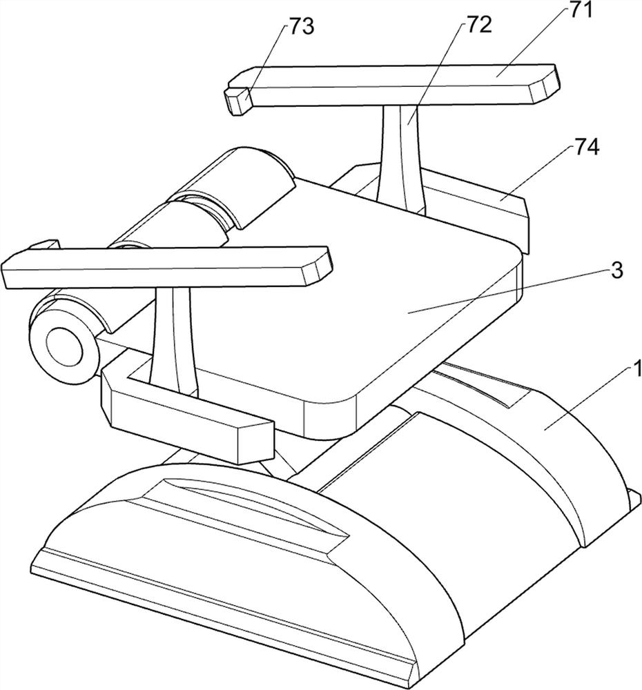
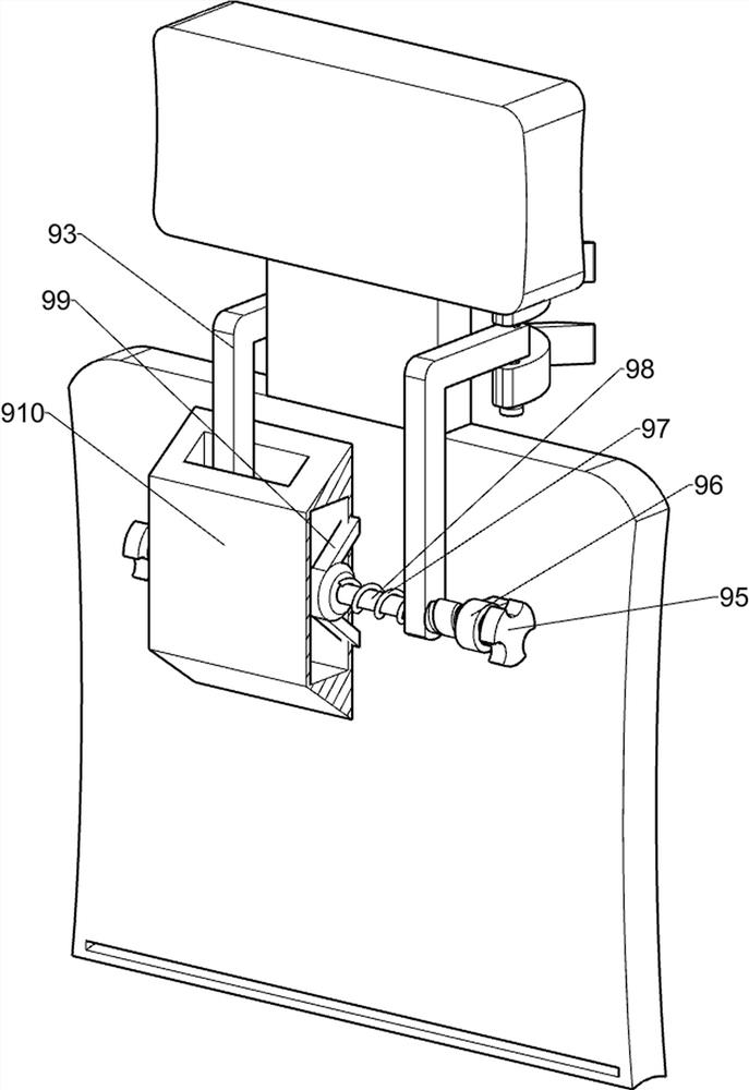
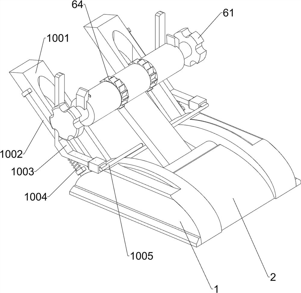
[0029] A kind of stomatology is used to be convenient to check the oral cavity inspection equipment, such as Figure 1-5 Shown, comprise supporting block 1, stabilizing block 2, supporting plate 3, guide rail plate 31, backrest plate 4, pillow plate 41, support mechanism 5, backrest mechanism 6 and supporting mechanism 7, stabilizing block 2 front and rear sides all are provided with There are support blocks 1, support mechanisms 5 are arranged between the support blocks 1, support plates 3 are provided on the support mechanisms 5, backrest mechanisms 6 are provided on the support mechanisms 5, supporting mechanisms 7 are provided on the support plates 3, backrest mechanisms 6 Backrest board 4 is arranged on it, three guide rail boards 31 are evenly established on the left side of support board 3 tops, backrest board 4 is connected with guide rail board 31 slidingly, and backrest board 4 top is provided with headrest board 41.
[0030] Support mechanism 5 comprises support bar...
Embodiment 2
[0035] On the basis of Example 1, such as figure 1 , Figure 6 , Figure 7 , Figure 7 , Figure 9 , Figure 10 , Figure 11 and Figure 12 As shown, a clamping mechanism 8 is also included, and the clamping mechanism 8 includes a connecting rod 81, a transmission belt 82, a mounting rod 83, a guide rail block 84, a clamping block 85, a rotating block 86, a second ratchet gear 87, and a connecting plate 88 , the second guide rod 89, the clamping plate 810, the second spring 811 and the third spring 812, the rear side of the second mounting block 74 on the rear side is rotatably provided with a mounting rod 83, and the rear side of the mounting rod 83 is provided with a connecting rod 81, Between the mounting bar 83 and the first rotating bar 63 rear sides, a drive belt 82 is connected by a drive wheel, a guide rail block 84 is provided in the middle of the connecting rod 81 top, and a sliding block 85 is provided on the guide rail block 84, and the block 85 is connected ...
PUM
 Abstract
Description
Claims
Application Information
 - R&D Engineer
- R&D Manager
- IP Professional
- Industry Leading Data Capabilities
- Powerful AI technology
- Patent DNA Extraction
Browse by: Latest US Patents, China's latest patents, Technical Efficacy Thesaurus, Application Domain, Technology Topic, Popular Technical Reports.
© 2024 PatSnap. All rights reserved.Legal|Privacy policy|Modern Slavery Act Transparency Statement|Sitemap|About US| Contact US: help@patsnap.com


