Mechanical welding and grinding integrated device

A mechanical welding, integrated technology, applied in the field of mechanical processing, to achieve good results, increase the scope of application, improve the applicability of the effect

Active Publication Date: 2022-03-11
HEBEI INSTITUTE OF ARCHITECTURE AND CIVIL ENGINEERING
View PDF4 Cites 0 Cited by
  • Summary
  • Abstract
  • Description
  • Claims
  • Application Information

AI Technical Summary

Problems solved by technology

[0004] Therefore, it is necessary to improve the disadvantages of repeated disassembly and assembly and more protrusions at the welding place in the welding and grinding process of the machinery in the prior art, and design a A mechanical welding and grinding integrated device that can take into account both welding and grinding of mechanical workpieces, and can effectively reduce the protrusion of the welding place

Method used


Image

  • Mechanical welding and grinding integrated device
  • Mechanical welding and grinding integrated device
  • Mechanical welding and grinding integrated device

Examples


Embodiment 1

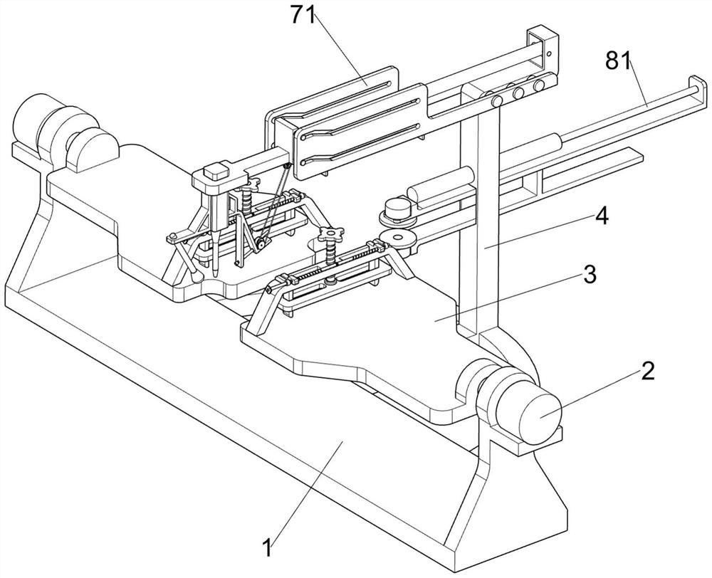
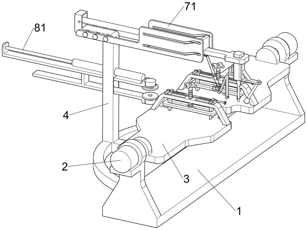
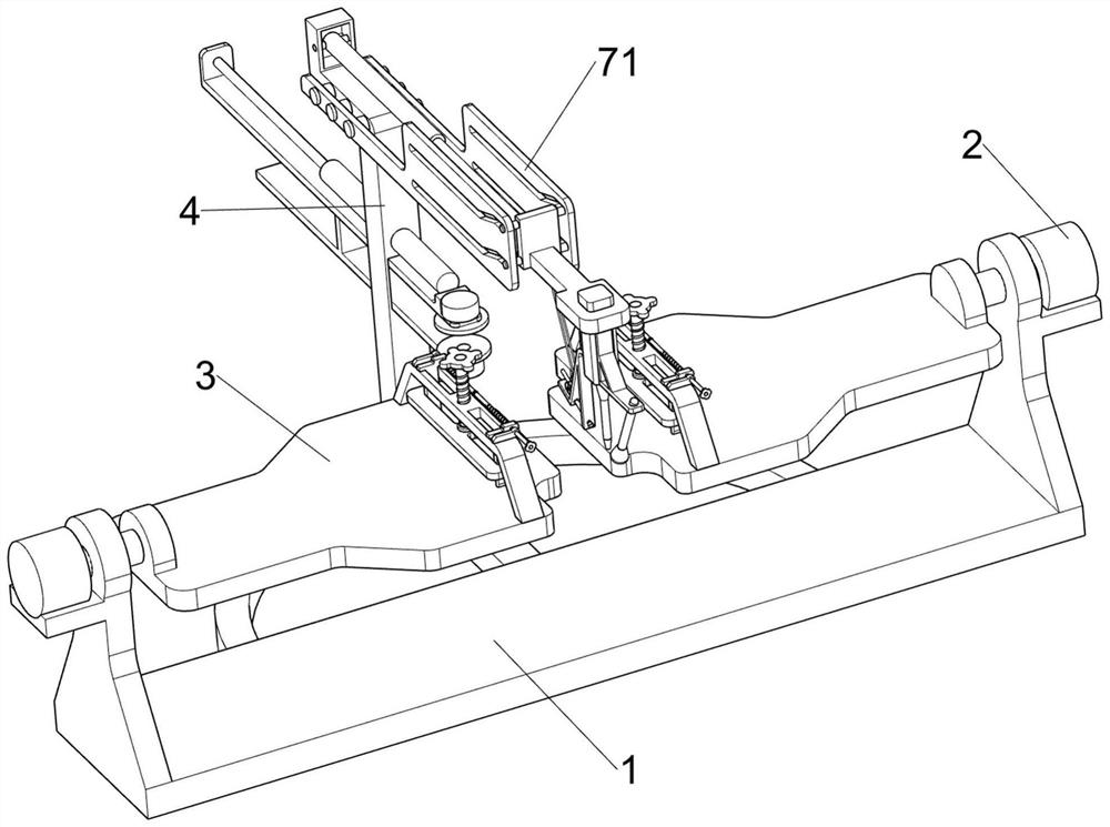
[0041] A mechanical welding and grinding integrated device, such as figure 1 , figure 2 , image 3 , Figure 4 , Figure 5 , Figure 6 As shown, it includes a bottom plate 1, a steering motor 2, a placement plate 3, a fixed main frame 4, an extrusion fixing component 5, a width limit adjustment component 6, a laser welding component 7, a grinding component 8 and a gas protection component 10. The upper part of the bottom plate 1 A steering motor 2 is symmetrically fixed, and the output shaft of the steering motor 2 is rotationally connected with the base plate 1. One end of the output shaft of the steering motor 2 is fixedly connected with a placement plate 3, and the steering motor 2 is used to drive the placement plate 3 to turn over. The side is fixedly connected with a fixed main frame 4, and the placing plate 3 is provided with an extruding and fixing assembly 5, which is used to extrude and limit the top of the workpiece, and the extruding and fixing assembly 5 is p...

Embodiment 2

[0052] On the basis of Example 1, such as Figure 7-11 As shown, an inert gas recovery assembly 9 is also included, and the inert gas recovery assembly 9 is arranged on the laser welding assembly 7. The inert gas recovery assembly 9 includes a fixed rack 91, a rotating gear 92, a large pulley 93, and a small pulley 94 , belt 95, air suction cylinder 96, the third rotating shaft 97, transmission gear 98 and fan blade 99, the fixed guide plate 71 bottom that is positioned at the right side is affixed with fixed rack 91, and the sliding seat 72 bottom rotatably is connected with rotating gear 92 The bottom of the special-shaped frame 76 is rotatably connected with a large pulley 93, the rotating gear 92 is fixedly connected with a small pulley 94, a belt 95 is wound between the large pulley 93 and the small pulley 94, and the bottom of the special-shaped frame 76 is fixedly connected with a suction ring. Air cylinder 96, on the air suction cylinder 96, the third rotating shaft 97...

Embodiment 3

[0055] On the basis of Example 2, such as Figure 5 As shown, it also includes a connecting rod 11, the bottom of the pole 82 is connected to the connecting rod 11 by welding, the connecting rod 11 passes through the fixed main frame 4, and the front part of the connecting rod 11 is also fixedly connected with a grinder 83.

[0056] During the forward movement of the pole 82 and its upper device, the connecting rod 11 will also move together, so that the two grinding machines 83 can simultaneously grind the welds on both sides of the mechanical workpiece, so that there is no need to put the The mechanical workpiece is turned over, saving unnecessary trouble.


PUM


Abstract

The invention relates to the field of machining, in particular to a mechanical welding and grinding integrated device which comprises a bottom plate, a steering motor, a placing plate, a fixing main frame and the like. Steering motors are symmetrically and fixedly connected to the upper portion of the bottom plate, output shafts of the steering motors are rotationally connected with the bottom plate, one ends of the output shafts of the steering motors are fixedly connected with a containing plate, and a fixing main frame is fixedly connected to the rear side of the lower portion of the bottom plate. A mechanical workpiece can be welded through the laser welding assembly, after welding is completed, a worker manually controls a second electric push rod to contract, two grinding machines grind the welding positions of the two faces of the mechanical workpiece at the same time, the trouble of repeated disassembly and assembly of the mechanical workpiece is avoided, and the machining efficiency of the mechanical workpiece is effectively improved; and the effect that the mechanical workpiece can be welded and polished at the same time is achieved.

Description

technical field [0001] The invention relates to the field of mechanical processing, in particular to a mechanical welding and grinding integrated device. Background technique [0002] In people's daily life, machinery is used more and more widely. Any modern industry and engineering field needs to apply machinery, such as automobiles, bicycles, clocks, cameras, etc. All in all, machinery is a tool that can help people reduce work difficulty or labor Devices, such as chopsticks, brooms, and tweezers, can be called machines. They are simple machines, and complex machines are composed of two or more simple machines. These more complex machines are usually called machines. [0003] Machinery usually needs to be processed, and in the process of automobile production, it is often necessary to weld automobile steel plates. After welding, a weld will be formed, and then the weld must be polished to facilitate the subsequent processing and application of the workpiece. Now There is ...

Claims


Application Information

Patent Timeline
Patent Type & Authority Applications(China)
IPC IPC(8): B23P23/00
CPCB23P23/00
Inventor 赵芳石树正高晓刚倪笑宇王烁陈立伟王少雷马立勇王振兴朱春华
Owner HEBEI INSTITUTE OF ARCHITECTURE AND CIVIL ENGINEERING
Why Eureka
Try Eureka