Soil sampler and soil sampling method

A soil fetcher and linear drive technology, applied in the field of soil research, can solve problems such as the difficulty of accurately controlling the depth of the ring knife entering and exiting the soil, and difficulty in pulling out, so as to achieve the effects of reducing resistance, increasing success rate, and improving accuracy

Pending Publication Date: 2022-03-04
ANHUI AGRICULTURAL UNIVERSITY
View PDF7 Cites 0 Cited by
  • Summary
  • Abstract
  • Description
  • Claims
  • Application Information

AI Technical Summary

Problems solved by technology

[0003] Aiming at the technical problems of the existing ring-knife soil fetcher, which is difficult to pull out after the middle ring knife enters the soil, and it is difficult to accurately control the depth of the ring knife entering and leaving the soil; The depth of the ring knife inserted into the soil improves the originality of the soil structure and the accuracy of nutrient determination

Method used


Image

  • Soil sampler and soil sampling method
  • Soil sampler and soil sampling method

Examples


Embodiment 1

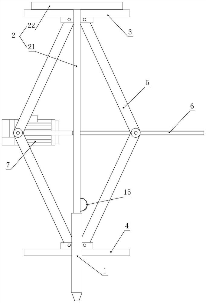
[0039] combined with figure 1 , this embodiment provides an earth taker, including a ring cutter 1 and a sleeve rod 2, the ring cutter 1 is fixedly connected to the lower end of the sleeve rod 2, and the ring cutter 1 and / or sleeve rod 2 are provided with a scale It also includes a booster assembly, which includes an upper clamping plate 3, a lower clamping plate 4 and a linear drive mechanism, the upper clamping plate 3 and the lower clamping plate 4 are detachably connected to the sleeve rod 2, and the lower clamping plate 4 is detachably connected to the sleeve rod 2. The clamping plate 4 is detachably connected to the ring knife 1, the linear drive mechanism is located between the upper clamping plate 3 and the lower clamping plate 4, and the upper clamping plate 3 and the lower clamping plate 4 pass through The linear drive mechanism drives relatively far away or close.

[0040]For the scale on the ring knife 1 and / or cover rod 2, determine according to the specific requ...

Embodiment 2

[0051] The present embodiment provides a kind of method for fetching soil, based on the soil fetching device described in embodiment 1, comprises the following steps:

[0052] S1. Connect the upper end of the sleeve rod 2 to the side of the upper clamping plate 3 of the booster assembly;

[0053] S2, set the metal wire 13 in the ring groove 12 of the inner wall of the ring knife 1, and place the pull ring 15 on the upper end of the pull rope 14 on the upper end of the lower clamping plate 4;

[0054] S3, vertically place the soil fetcher assembled in step S2 at the soil fetching point;

[0055] S4. Collide with the upper clamping plate 3, and drive the screw 6 to rotate through the motor to drive the ring knife 1 to move vertically downward until the lower clamping plate 4 touches the surface of the soil layer, thereby restricting the ring knife 1 from entering and exiting the soil through the lower clamping plate 4 depth;

[0056] S5. Keep the position of the ring knife 1 u...


PUM


Abstract

The invention discloses a soil sampler and a soil sampling method, and relates to the technical field of soil research. The soil sampler comprises a cutting ring and a loop bar, the cutting ring is fixedly connected to the lower end of the loop bar, and the cutting ring and / or the loop bar are / is provided with scales; the device further comprises a power assisting assembly, the power assisting assembly comprises an upper clamping plate, a lower clamping plate and a linear driving mechanism, the upper clamping plate is detachably connected with the sleeve rod, the lower clamping plate is detachably connected with the cutting ring, and the linear driving mechanism is located between the upper clamping plate and the lower clamping plate. And the upper clamping plate and the lower clamping plate are driven by the linear driving mechanism to be relatively far away from or close to each other, so that the depth of the cutting ring inserted into the soil can be accurately controlled, and the soil structure and nutrient measurement accuracy is improved. The soil sampling method is based on the soil sampler, the depth of the cutting ring inserted into the soil can be accurately controlled, and meanwhile, the soil sample in the cutting ring can be taken out under the condition that the soil structure is prevented from being damaged.

Description

technical field [0001] The invention relates to the technical field of soil research, in particular to a soil fetching device and a soil fetching method. Background technique [0002] In basic agricultural scientific research, it is often necessary to determine soil structure and nutrients. During the soil extraction process, in order to ensure the accuracy of the soil extraction depth and ensure that the soil extraction process does not destroy the original structure of the soil, a ring knife soil access device is generally used. Most of the existing ring-knife soil extractors directly insert the ring-knife into the soil with a connecting rod, but the soil is generally taken during the alternation of planting and the growth period of crops. Due to different regions and different periods, the soil moisture content and soil viscosity are different. The resistance when causing soil extraction is different, there is difficulty in pulling out the ring cutter and the situation t...

Claims


Application Information

Patent Timeline
Patent Type & Authority Applications(China)
IPC IPC(8): G01N1/04
CPCG01N1/04
Inventor 丁文金张海鹏陈园园方凡黄正来
Owner ANHUI AGRICULTURAL UNIVERSITY
Why Eureka
Try Eureka