Punching device and punching method for foundation horizontal bar planting

A drilling device and basic technology, applied in drilling/drilling equipment, measuring/indicating equipment, portable drilling rigs, etc., can solve the problems of difficulty in precise control of manual drilling depth, inability to guarantee construction quality, and increased safety risks, etc. Achieve the effect of improving operation efficiency, ensuring construction quality and reducing safety risks

Inactive Publication Date: 2022-02-15
HEBEI INSTALLATION ENG
View PDF6 Cites 1 Cited by
  • Summary
  • Abstract
  • Description
  • Claims
  • Application Information

AI Technical Summary

Problems solved by technology

[0003] Reinforcement drilling is generally performed by manual hand-held electric drills, which has low labor efficiency. If the working hours are too long, work-related accidents due to work negligence or fatigue will occur, which increases safety risks; and the depth of manual drilling is difficult to accurately control. quality cannot be guaranteed

Method used


Image

  • Punching device and punching method for foundation horizontal bar planting
  • Punching device and punching method for foundation horizontal bar planting

Examples


Embodiment 1

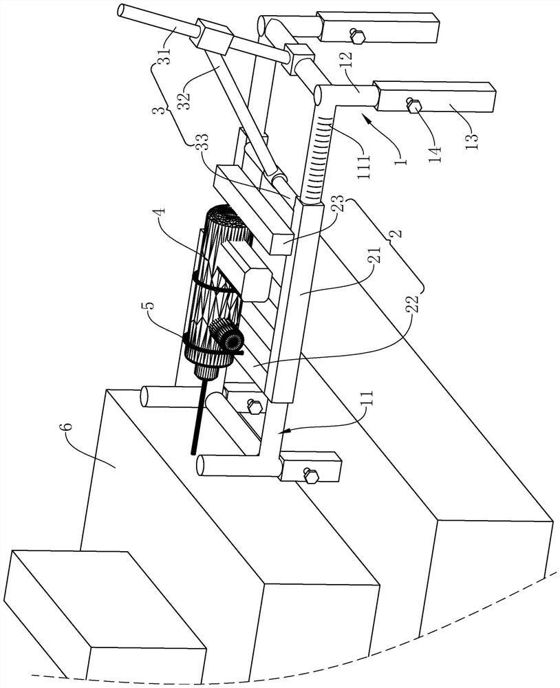
[0040] refer to figure 1 , The punching device used for the foundation horizontal planting bar includes an adjustable base bracket 1, a sliding frame 2 and a stroke control mechanism 3. The adjustable base support 1 is placed on the ground or the surface of the foundation 6 of the structure, and the height of the adjustable base support 1 itself can be adjusted. The sliding frame 2 is installed on the adjustable base support 1 and is slidingly matched with the adjustable base support 1 . The hand-held electric drill 4 is located on the top of the sliding frame 2 and is detachably connected with the sliding frame 2. The stroke control mechanism 3 is connected with the adjustable base support 1 and the sliding frame 2 at the same time, and the stroke control mechanism 3 is used to control the moving distance and speed of the sliding frame 2 .

[0041] The adjustable base bracket 1 is used as the installation carrier of the sliding frame 2, the hand-held electric drill 4 and th...

Embodiment 2

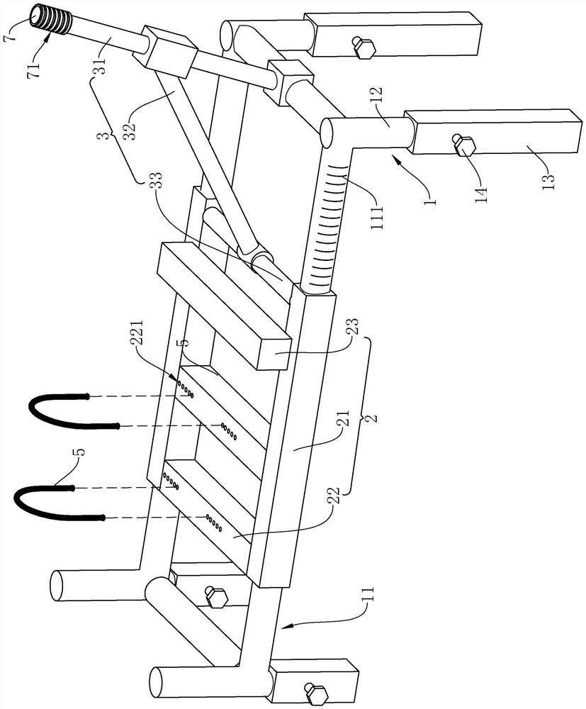
[0050] refer to figure 2 The difference between Embodiment 2 and Embodiment 1 is that the connecting beam 22 is uniformly provided with a plurality of mounting holes 221 along its own extending direction, and any mounting hole 221 is used for inserting U-shaped forks 5 of different specifications. Because in actual construction, the specification of steel bar is different, and the depth and aperture that need punching are different, therefore need to adopt the hand-held electric drill 4 of different specification, just need to support the U-shaped fork 5 of different size, by opening multiple A mounting hole 221 can facilitate the matching of the connecting beam 22 with U-shaped forks 5 of different sizes, thereby realizing the fixed installation of the hand-held electric drill 4 of different specifications.

[0051] refer to figure 2 The end of the active push rod 31 away from the rectangular frame 11 is fixedly sleeved with an anti-slip handle 7, and the outer peripheral ...


PUM


Abstract

The invention relates to the technical field of building construction, in particular to a punching device and a punching method for foundation horizontal bar planting. The punching device comprises an adjustable base support, a sliding frame and a stroke control mechanism, wherein height of the adjustable base support can be adjusted, and the adjustable base support can be used for being placed on the ground or a surface of a building foundation; the sliding frame is installed on the adjustable base support in a sliding mode, and a handheld electric drill is detachably connected with the sliding frame; and the stroke control mechanism is connected with the adjustable base support and the sliding frame, and the stroke control mechanism is used for controlling a moving distance of the sliding frame relative to the adjustable base support. The punching method comprises the steps that S1, height and levelness of the adjustable base support are adjusted; S2, the handheld electric drill is installed; S3, the handheld electric drill is started; and S4, a driving push rod pushes the handheld electric drill to accurately drill holes. According to the invention, the operation efficiency can be improved, the safety risk is reduced, the punching depth is accurately controlled, and the construction quality is guaranteed.

Description

technical field [0001] The present application relates to the technical field of building construction, in particular to a punching device and a punching method for foundation horizontal reinforcement. Background technique [0002] During the reconstruction of the factory area, it is usually necessary to enlarge the cross-section of the original old foundation and increase the number of horizontal steel bars on the original old foundation, resulting in a large amount of rebar planting work. [0003] Reinforcement drilling is generally performed by manual hand-held electric drills, which has low labor efficiency. If the working hours are too long, work-related accidents due to work negligence or fatigue will occur, which increases safety risks; and the depth of manual drilling is difficult to accurately control. Quality cannot be guaranteed. Contents of the invention [0004] In order to improve operation efficiency, reduce safety risks, accurately control the depth of dri...

Claims


Application Information

Patent Timeline
Patent Type & Authority Applications(China)
IPC IPC(8): B23B45/02B23Q17/22
CPCB23B45/02B23Q17/22
Inventor 张淼吴皓李博刘竞劼赵耀宗王润王海庆樊会娜李静芳
Owner HEBEI INSTALLATION ENG
Why Eureka
Try Eureka