
Non-fixed cathode electrolytic machining device

A cathode electrolysis and processing device technology, which is applied in the direction of electric processing equipment, electrochemical processing equipment, processing electrodes, etc., can solve the problem that it is difficult to achieve high-precision electrolytic processing on the inner surface of the casing, so as to reduce stray corrosion and ensure Machining accuracy, the effect of ensuring the airtight state

Active Publication Date: 2022-03-04
CHINA HANGFA SOUTH IND CO LTD
View PDF10 Cites 0 Cited by
  • Summary
  • Abstract
  • Description
  • Claims
  • Application Information

AI Technical Summary

Problems solved by technology

[0004] The present invention provides a non-fixed cathode electrolytic machining device to solve the technical problem that it is difficult to achieve high-precision electrolytic machining on the inner surface of the casing

Method used


Image

  • Non-fixed cathode electrolytic machining device
  • Non-fixed cathode electrolytic machining device
  • Non-fixed cathode electrolytic machining device

Examples


Embodiment Construction

[0026] The embodiments of the present invention will be described in detail below with reference to the accompanying drawings, but the present invention can be implemented in various ways defined and covered below.

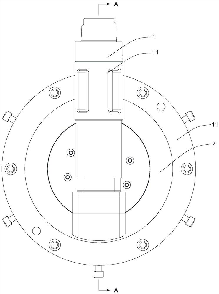
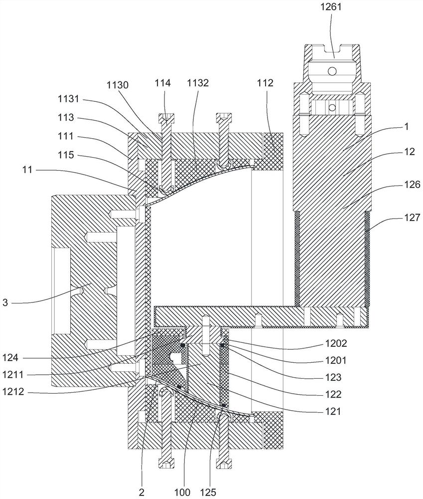
[0027] Figure 2 to Figure 5 Commonly shown is the non-fixed cathode electrolytic machining device 1 provided by the embodiment of the present invention, which is used for electrolytic machining the inner surface of the casing of an aero-engine, and can complete the machining of the casing cavity with high precision and high efficiency.

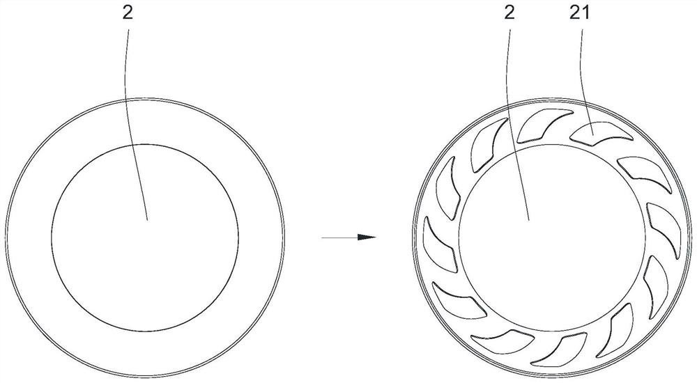
[0028] exist figure 1 shows a casing 2 suitable for the non-fixed cathode electrolytic processing device 1, the casing 2 needs to process a plurality of cavities 21 on the inner surface, and a plurality of cavities 21 along the machine The circumferential equidistant arrangement of box 2.

[0029] Please combine figure 2 and image 3 , the non-fixed cathode electrolytic processing device 1 includes an anode clamping mechanis...


PUM


Abstract

The non-fixed cathode electrolytic machining device comprises an anode clamping mechanism used for clamping a cartridge receiver and a cathode machining mechanism used for stretching into the inner side of the cartridge receiver, the cathode machining mechanism comprises a cathode cutter, a flow guide part and a first sealing ring, and the flow guide part is arranged around the periphery of the cathode cutter; the flow guide part is used for abutting against the inner surface of the machine box and enabling an electrolytic machining space to be formed between the machine box and the end face of the cathode cutter, one of the cathode cutter and the flow guide part is provided with a feeding groove, and the other one of the cathode cutter and the flow guide part is provided with a limiting flange clamped in the feeding groove. The feeding groove extends in the feeding direction of the cathode cutter to form a feeding space for the limiting flange to move, and the first sealing ring is pressed in the feeding space in an elastic mode. According to the non-fixed cathode electrolytic machining device, the cathode cutter can move relative to the flow guide part to achieve feeding, the stray corrosion phenomenon during electrolytic machining is reduced, and the machining precision of a casing cavity is improved.

Description

technical field [0001] The invention relates to the technical field of electrolytic machining, in particular to a non-fixed cathode electrolytic machining device. Background technique [0002] At present, for the processing of the cavity on the inner surface of the casing of the aero-engine, the machining method is usually adopted, firstly shape the shape by stamping, and then remove the allowance by turning. It is easy to cause deformation of the casing and reduce machining accuracy. [0003] In this regard, electrolytic machining is a special processing technology based on the principle of electrochemical anodic dissolution to remove material from the workpiece. The cavity is formed at one time, no follow-up process modification is required, and the processing efficiency is high. However, since the cavity to be processed on the casing is located inside the casing, it is difficult to feed the cathode cutter, so the fixed cathode processing method is usually used, that is,...

Claims


Application Information

Patent Timeline
Patent Type & Authority Applications(China)
IPC IPC(8): B23H3/00B23H7/30B23H3/04B23H3/10B23H11/00
CPCB23H3/00B23H7/30B23H3/04B23H3/10B23H11/003
Inventor 谷民凯吴小燕王建良岳磊苏庆怀易鹏张昌昊赵建社
Owner CHINA HANGFA SOUTH IND CO LTD
Learn More