
Light guiding structure, lateral entrance type backlight module, and display device

A technology of side-illuminated backlight and light guide structure is applied in the field of display equipment, which can solve the problems of high cost of light guide plate 4', fragile printing dots, long dot design verification period, etc., so as to improve the utilization rate of light energy and the reliability of use. , Improve structural reliability and service life, improve the effect of light energy utilization and reliability

Active Publication Date: 2019-10-08
SHENZHEN SKYWORTH RGB ELECTRONICS CO LTD
View PDF13 Cites 3 Cited by
  • Summary
  • Abstract
  • Description
  • Claims
  • Application Information

AI Technical Summary

Problems solved by technology

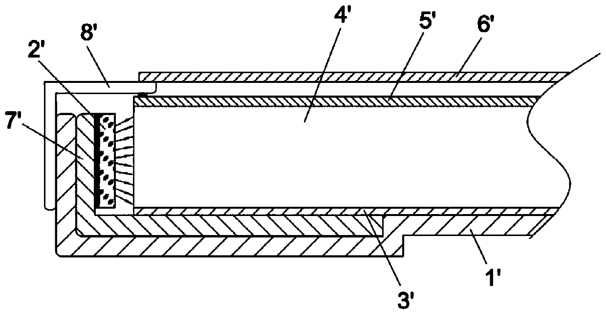
It mainly has the following problems: the cost of the light guide plate 4' is high, accounting for about 30% of the cost of the side-entry module; 2' The light energy emitted cannot be incident, causing problems such as light leakage, bright edges, and poor reliability
In addition, the dot design and verification period of the light guide plate 4' is long, the production process is complicated, and the yield rate is low; the dots printed on the light guide plate 4' are fragile and easily scratched and damaged during transportation, resulting in poor subjective visual effects

Method used


Image

  • Light guiding structure, lateral entrance type backlight module, and display device
  • Light guiding structure, lateral entrance type backlight module, and display device
  • Light guiding structure, lateral entrance type backlight module, and display device

Examples


Embodiment Construction

[0037] The technical solutions of the present invention will be further described below in conjunction with the accompanying drawings and through specific implementation methods. It should be understood that the specific implementation manners described here are only used to explain the present invention, rather than to limit the present invention. In addition, it should be noted that, for the convenience of description, only the parts related to the present invention are shown in the drawings but not all of them.

[0038] In describing the present invention, it is to be understood that the terms "upper", "lower", "front", "rear", "left", "right", "vertical", "horizontal", "top", The orientation or positional relationship indicated by "bottom", "inner", "outer", etc. is based on the orientation or positional relationship shown in the drawings, and is only for the convenience of describing the present invention and simplifying the description, rather than indicating or implying...


PUM


Abstract

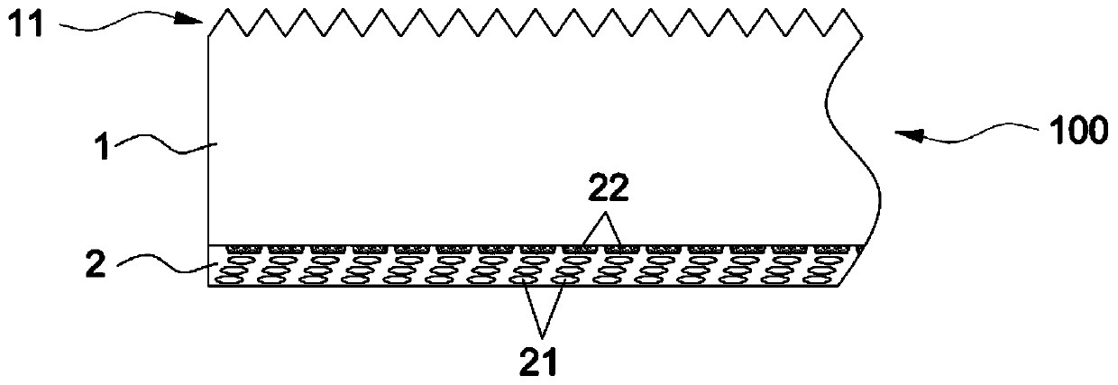
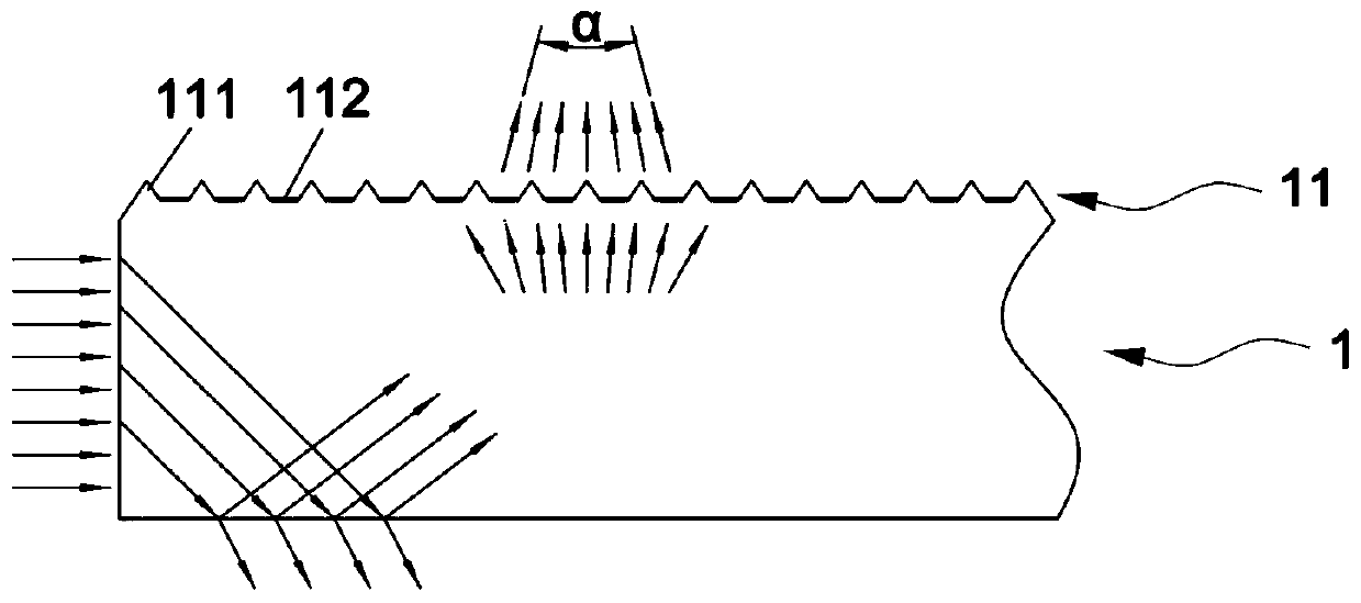
The invention, which relates to the technical field of display devices, specifically discloses a light guiding structure, a lateral entrance type backlight module, and a display device. The light guiding structure comprises a light guiding layer and a reflective layer that are integrally bonded; a light condensation structure for collecting emitted light is arranged at a light emitting surface ofthe light guiding layer; a reflective layer is disposed on the back surface of the light guiding layer; and scattering particles are arranged on the light reflective surface of the reflective layer and are used for scattering light entering the light reflective surface. The light guiding layer and the reflective layer are made of PET. With the light guiding structure, the light energy loss can bereduced effectively and the utilization of light energy can be improved. The integrated design of the reflection, light guiding and brightening is realized; a reflection sheet, a light guide plate, aprism sheet, and a diffusion sheet in the conventional lateral entrance type backlight module can be replaced; the longitudinal structure of the backlight module can be simplified; the cost of the photovoltaic module can be lowered; and the light energy utilization and reliability can be improved. Since the light guiding layer and the reflective layer are made of PET, the light guiding structure enables the cost to be lowered by being compared with the traditional light guiding plate. Because of the flexible material, the structural compatibility is improved and the project development is promoted.

Description

technical field [0001] The invention relates to the technical field of display devices, in particular to a light guide structure, a side-entry backlight module and a display device. Background technique [0002] A display device is a device that can output images or sensory information, including televisions, monitors, and advertising machines. A display device generally includes a backlight module and a liquid crystal glass. The backlight module can be divided into a side-type backlight module and a direct-type backlight module according to the setting position of the light incident surface. The structure of the commonly used side-type backlight module is as follows: figure 1 As shown, it includes a backplane 1' and a light guide plate 4' installed on the backplane 1', a reflective sheet 3' is set between the light guide plate 4' and the backplane 1', and an optical film is set on the light guide plate 4' 5', the middle frame 8' frames the above-mentioned back plate 1', r...

Claims


Application Information

Patent Timeline
Patent Type & Authority Applications(China)
IPC IPC(8): G02B6/00G02F1/13357
CPCG02B6/0036G02B6/0055G02F1/133615
Inventor 刘欣尤君平洪文生余彦飞朱寿天兰兵李圣赵媛媛王小培
Owner SHENZHEN SKYWORTH RGB ELECTRONICS CO LTD
Learn More