
Forced air cooling type laser cooling system

A cooling system and forced air cooling technology, which is applied to laser cooling devices, lasers, laser components, etc., can solve the problems of reduced thermal conductivity and heat transfer coefficient, high instantaneous power, and large calorific value, and achieve strong heat transfer capability and environmental protection The effect of adaptability, small environmental restrictions, and large heat transfer

Pending Publication Date: 2022-03-01
上海玖热智能科技有限公司
View PDF0 Cites 1 Cited by
  • Summary
  • Abstract
  • Description
  • Claims
  • Application Information

AI Technical Summary

Problems solved by technology

[0006] 1. With the increase in the power of electronic equipment, single-phase flow circulation cooling is gradually difficult to meet the thermal management requirements under high heat flux density conditions
[0007] 2. The existing equipment adopts the method of immersion phase change cooling for the part with the largest heat generation of the laser, but the direct immersion cooling of this scheme cannot actually achieve a high heat transfer coefficient, and when the laser is working, its instantaneous power is too high, and If the heat is too large, film boiling may occur at this time, and the thermal conductivity and heat transfer coefficient will be seriously reduced
Therefore, the use of this phase change cooling method still cannot solve the heat dissipation problem of high-power lasers
[0008] 3. The existing equipment adopts immersion phase-change cooling for the parts with the largest heat generation of the laser, but the direct immersion cooling of this scheme cannot actually achieve a high heat transfer coefficient, and when the laser is working, its instantaneous power is too high. If the heat is too large, film boiling may occur at this time, and the thermal conductivity and heat transfer coefficient will be seriously reduced
Therefore, the use of this phase change cooling method still cannot solve the heat dissipation problem of high-power lasers

Method used


Image

  • Forced air cooling type laser cooling system
  • Forced air cooling type laser cooling system

Examples


Embodiment Construction

[0023] The present invention will be further described below. The following examples are only used to illustrate the technical solution of the present invention more clearly, but not to limit the protection scope of the present invention.

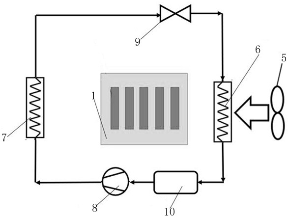
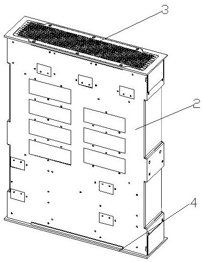
[0024] As shown in the figure, a forced air-cooled laser cooling system of the present invention includes laser heating components, the laser heating components 1 are installed in a box body 2, and an air inlet 3 is provided on one side of the box body 2 , the other side is provided with an air outlet 4, the air inlet 3 is connected with an air supply device 5, the air inlet 3 is provided with a first cooling device 6, and the first cooling device 6 is located between the air supply device 5 and the air inlet 3, the air outlet 4 is provided with a second cooling device 7.

[0025] The air is blown into the box body 2 through the air supply device 5, and the laser heating component 1 is dissipated by air cooling. At the same time, the first...


PUM


Abstract

The invention discloses a forced air cooling type laser cooling system. Comprising a laser heating component, the laser heating component is installed in a box body, one side of the box body is provided with an air inlet, the other side of the box body is provided with an air outlet, the air inlet is connected with an air supply device, the air inlet is provided with a first cooling device, and the first cooling device is located between the air supply device and the air inlet. And the air outlet is provided with a second cooling device. The cooling system provided by the invention adopts an air cooling mode to cool a heating part of the laser, and adopts an external cooling working medium to cool air, so that the cooling system has larger heat exchange amount, is less limited by the environment, can be used in a high-temperature environment, is more compact in structure, and has stronger heat exchange capability and environmental adaptability.

Description

technical field [0001] The invention relates to a forced air-cooled laser cooling system, which belongs to the technical field of laser generators. Background technique [0002] A laser is a device capable of emitting laser light. It is the core equipment for military and high-precision processing, and it is also one of the weapons and equipment that countries focus on developing. A laser is mainly composed of a pump source, a laser medium and a resonant cavity. Among them, the effective heat dissipation of the pump source is an important guarantee for the safe and stable operation of the laser. The current main cooling methods for lasers are as follows: [0003] 1. Forced air cooling is the most widely used heat dissipation method at present. Aluminum or copper heat sinks are usually used to increase the convection area, and then fans are used for forced convection air cooling to achieve the effect of heat dissipation. The design of the heat sink and the cooperation of t...

Claims


Application Information

Patent Timeline
IPC IPC(8): H01S3/04H01S5/024
CPCH01S3/0404H01S3/0407H01S5/02423H01S5/02407
Inventor 廖博文郭贻玲
Owner 上海玖热智能科技有限公司
Learn More