Thermal spraying treatment system and thermal spraying treatment method

A processing system, thermal spraying technology, applied in coating, spraying device, melt spraying and other directions, can solve the problems of operator injury, easy axis deviation, irregular splashing of coating material, etc., to achieve uniform coating thickness , to avoid the effect of paint splashing

Pending Publication Date: 2022-03-01
张树国
View PDF1 Cites 3 Cited by
  • Summary
  • Abstract
  • Description
  • Claims
  • Application Information

AI Technical Summary

Problems solved by technology

[0003] The above-mentioned thermal spraying device and the existing thermal spraying treatment system also have the following problems in the actual use process: (1) the incident angle of the coating material sprayed on the workpiece surface through the nozzle is relatively large, and the coating material will contact the workpiece surface after contacting the workpiece surface. There will be a large impact force between them, resulting in irregular splashing of the coating material, which is likely to cause injury to the operator; (2) During the process of spraying the surface of the workpiece, ensure that the axis of the workpiece is easily shifted when the workpiece is rotated, causing the surface of the workpiece to be coated. Uneven layer thickness

Method used


Image

  • Thermal spraying treatment system and thermal spraying treatment method
  • Thermal spraying treatment system and thermal spraying treatment method
  • Thermal spraying treatment system and thermal spraying treatment method

Examples


Embodiment Construction

[0030] The embodiments of the present invention will be described in detail below with reference to the accompanying drawings, but the present invention can be implemented in many different ways defined and covered by the claims.

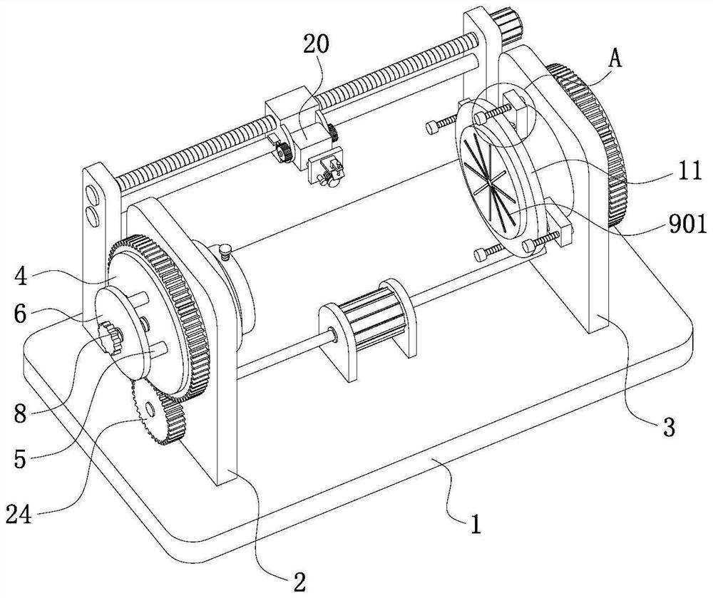
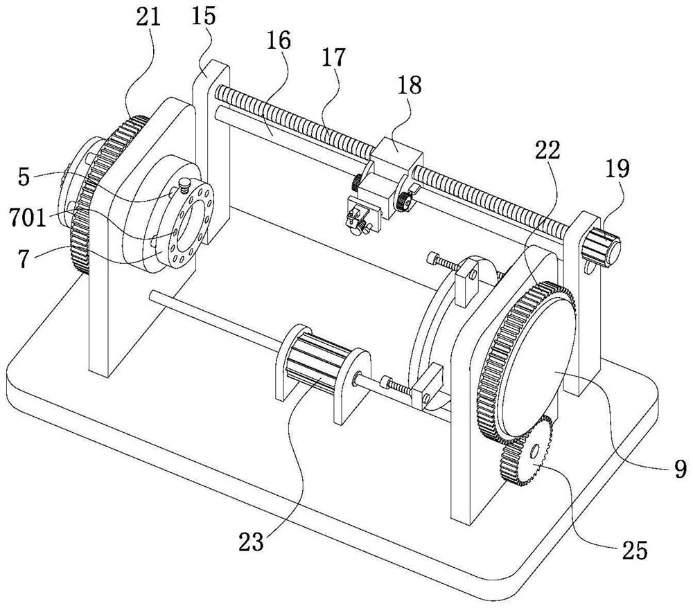
[0031] Such as figure 1 , figure 2 and Figure 6 As shown, the present embodiment provides a thermal spraying treatment system, including a horizontal base plate 1, the upper surface of the base plate 1 is fixedly installed with a first vertical plate 2 and a second vertical plate 3 parallel to each other; the first vertical plate The first horizontal column 4 that runs through the first vertical plate 2 is rotatably installed on the 2, and several horizontal rods 5 are evenly installed on the first horizontal column 4 along its circumference, and the horizontal rods 5 slide axially along the first horizontal column 4 Through the first horizontal column 4; the ends of several horizontal bars 5 away from the second vertical plate 3 are fixedly con...


PUM


Abstract

The invention belongs to the technical field of thermal spraying, and particularly relates to a thermal spraying treatment system and a thermal spraying treatment method.In the thermal spraying treatment system, a spraying mechanism can adjust the position and the angle of a spraying head, so that the extension line of the spraying head is tangent to the surface of a workpiece, and the spraying head is fixed to the surface of the workpiece; irregular splashing when paint sprayed by the spray head makes contact with the surface of the workpiece is avoided, meanwhile, the paint is blocked through a material blocking plate, and paint splashing is further avoided; the position of a workpiece is adjusted through a positioning block, the axis of the workpiece, the axis of a first horizontal column and the axis of a second horizontal column are kept in a coincident state, the workpiece abuts against the second horizontal column through a pressing ring, and meanwhile the end face of the workpiece is tightly sucked to the end face of the pressing ring through the air pressure effect; therefore, it is guaranteed that the first horizontal column and the second horizontal column can drive the workpiece to rotate at a constant speed when rotating, the axis does not deviate when the workpiece rotates, and the surface coating thickness of the workpiece is guaranteed.

Description

technical field [0001] The invention belongs to the technical field of thermal spraying, and in particular relates to a thermal spraying treatment system and a thermal spraying treatment method. Background technique [0002] Thermal spraying refers to heating and melting the coating material, atomizing it into extremely fine particles with high-speed airflow, and spraying it onto the surface of the workpiece at a high speed to form a coating; different coating materials can be selected according to the needs to obtain wear-resistant One or several properties in terms of damage, corrosion resistance, oxidation resistance, heat resistance, etc. CN208604189U discloses a hydraulic support column multi-station automatic thermal spraying device, comprising a base plate, a connecting seat, a moving wheel, a lateral moving frame, a moving box, a lifting frame, a spraying head, a connecting box, a control panel, auxiliary wheels, a casing, and a battery , switch, cooling cylinder st...

Claims


Application Information

Patent Timeline
IPC IPC(8): C23C4/12B05B13/02
CPCC23C4/12B05B13/0228B05B13/0278
Inventor 张树国
Owner 张树国
Why Eureka
Try Eureka