


Quick Research
Generate reliable direction feasibility study reports for your R&D in just a few steps.

Technical Q&A
Discover and master advanced knowledge NOW. Basics, ideas, possibilities, all at once.

Find Solutions
As an expert in R&D theories, this can generate solutions to your technical problems instantly.

Evaluate Feasibility
Analyze your overall solution with one click, know your potential R&D risks in advance.

Monitor Landscape
Get weekly tech updates, stay abreast of the latest tech innovations and key insights.
A kind of intelligent polishing equipment for electric vehicle half shaft
A technology for electric vehicles and equipment, applied in grinding/polishing equipment, metal processing equipment, machine tools for surface polishing, etc., can solve the problems of splashing polishing powder, difficult cleaning of equipment, affecting equipment operation performance and product quality, etc. Avoid irregular splashing of iron filings and improve cleaning effect
- Summary
- Abstract
- Description
- Claims
- Application Information
AI Technical Summary
Problems solved by technology
Method used
Image

Examples
Embodiment 1
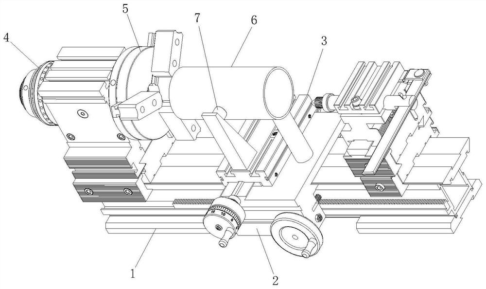
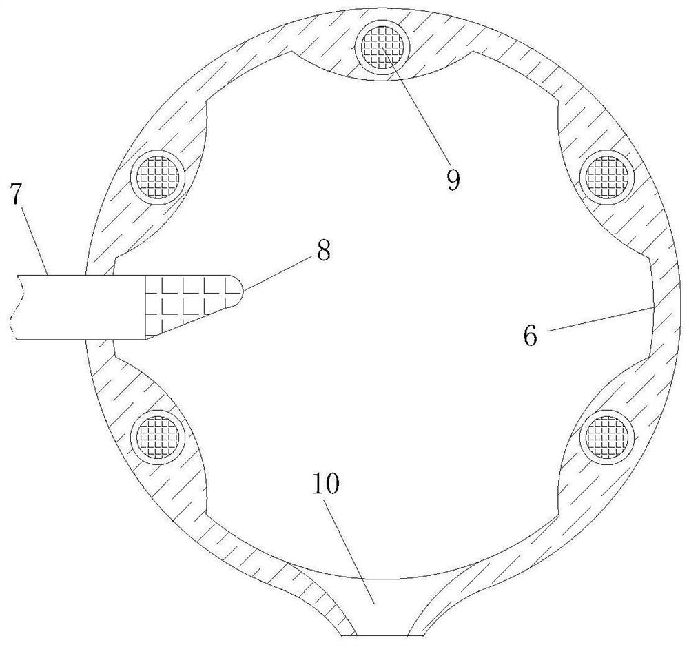
[0030] Such as Figure 1 to Figure 5As shown, a kind of intelligent polishing equipment for electric vehicle semi-axis according to the present invention includes a base 1; the upper side of the base 1 is slidably connected to a No. 1 operating table 2; No. 1 console 3; a motor 4 and a fixture disk 5 are installed on the upper side of the base 1, and the fixture disk 5 is driven to rotate by the motor 4; a sleeve 6 is fixedly connected to the upper side of the No. 1 console 2 through a bracket, and the sleeve The cylinder 6 is concentric with the fixture disc 5; the upper side of the No. 2 operating table 3 is fixedly connected with a push rod 7 through a bracket, and the push rod 7 is slidingly connected with the sleeve 6; the push rod 7 extends to one end of the sleeve 6 A grinding head 8 is fixedly connected; an electromagnet strip 9 is installed in the inner wall of the sleeve 6; a chip discharge port 10 is provided at the bottom of the sleeve 6; Through the sleeve 6, the...
Embodiment 2
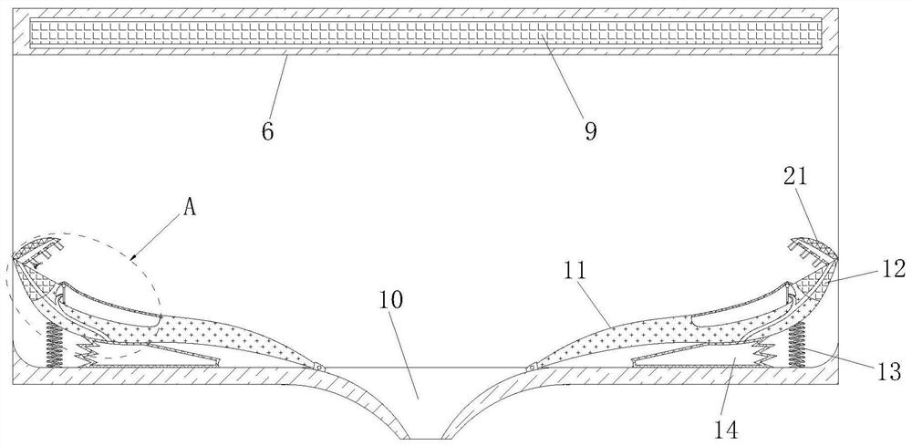
[0039] Such as Figure 6 As shown in Comparative Example 1, as another embodiment of the present invention, an auger 29 is rotatably connected to the nozzle 23 away from the magnetic block 12 through a bracket; A diverter block 30 is connected; several dispersed channels 31 are provided in the diverter block 30; when the air flow passes through the nozzle 23, the auger 29 is driven to rotate, and then the diverter block 30 is driven to rotate. Dispersed, along with the rotation of the diverter block 30, a spiral airflow is generated, which increases the range of action of the airflow, thereby improving the cleaning area of the eggplant-shaped block 11 by the airflow.
[0040] The outlet end of the dispersed channel 31 is slidingly and sealedly connected with a blocking ball 32; an elastic strip 33 is fixedly connected between the blocking ball 32 and the inner wall of the dispersed channel 31; Push the blocking ball 32 away, when there is no air flow in the dispersed channe...
PUM
 Abstract
Description
Claims
Application Information
 - R&D Engineer
- R&D Manager
- IP Professional
- Industry Leading Data Capabilities
- Powerful AI technology
- Patent DNA Extraction
Browse by: Latest US Patents, China's latest patents, Technical Efficacy Thesaurus, Application Domain, Technology Topic, Popular Technical Reports.
© 2024 PatSnap. All rights reserved.Legal|Privacy policy|Modern Slavery Act Transparency Statement|Sitemap|About US| Contact US: help@patsnap.com