In-vitro vascular tissue-like model with fluid environment and application of in-vitro vascular tissue-like model

A fluid and liquid technology, applied in the field of in vitro vascular tissue model, can solve the problems of high cost, long time and complicated operation.

Active Publication Date: 2022-03-01
UNIVERSITY OF CHINESE ACADEMY OF SCIENCES
View PDF16 Cites 0 Cited by
  • Summary
  • Abstract
  • Description
  • Claims
  • Application Information

AI Technical Summary

Problems solved by technology

At present, the models for studying blood vessels mainly adopt a variety of animal models and isolated blood vessel models in an in vitro fluid environment. These models need to be sacrificed at the expense of animals, and are time-consuming, cumbersome and costly.

Method used


Image

  • In-vitro vascular tissue-like model with fluid environment and application of in-vitro vascular tissue-like model
  • In-vitro vascular tissue-like model with fluid environment and application of in-vitro vascular tissue-like model
  • In-vitro vascular tissue-like model with fluid environment and application of in-vitro vascular tissue-like model

Examples


Embodiment 1

[0046] Embodiment 1. Fabrication of microfluidic chip and fluid parameter setting of circulation system

[0047] 1. Fabrication of microfluidic chip

[0048] A. Design chip structure and print mask.

[0049] B. Preparation of silicon wafer template

[0050] Soak a 100mm monocrystalline silicon wafer in Piranha solution (98% concentrated sulfuric acid / 30% hydrogen peroxide = 2 / 1) for 30 minutes; take out the silicon wafer, wash it with a large amount of ultrapure water, and dry it at 200°C for 30 minutes; place the silicon wafer in a spin gel Coat photoresist SU-82035 on the instrument to form a film layer with a thickness of about 100 μm; place the silicon wafer coated with photoresist at 65 ° C / 5 min and 90 ° C / 30 min for baking treatment; the prepared mask (fluid The channel part is the light-transmitting part) is attached to the silicon wafer coated with photoresist, and is irradiated with high-intensity ultraviolet light for 60s; the exposed silicon wafer is baked at...

Embodiment 2

[0076] Example 2. Construction of In Vitro Vascular Tissue Model in Circulating Fluid Environment

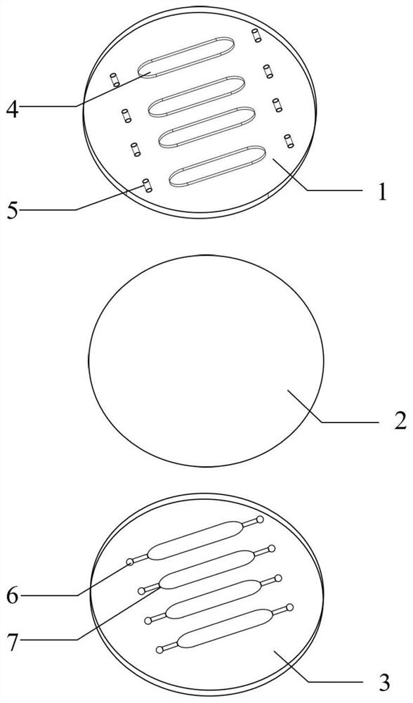
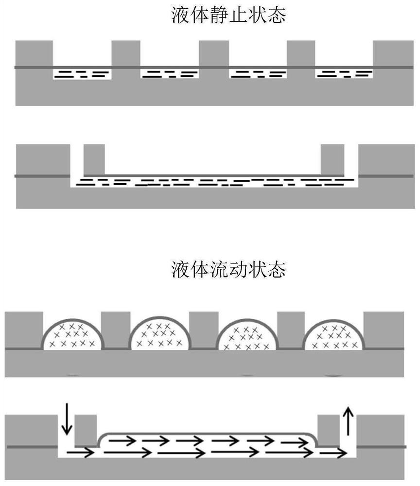
[0077] The cells are injected into the microchannel 7 of the microfluidic chip to make them attach and grow on the middle PDMS deformable layer 2, and after reaching fusion, they are connected to the fluid circulation system. By changing the flow velocity or the thickness of the middle PDMS deformable layer 2, the corresponding fluid shear force, fluid pressure and tensile force acting on the cells are obtained. Factors that induce and interfere with the occurrence of vascular lesions are introduced by changing the composition of the medium.


PUM

PropertyMeasurementUnit
thicknessaaaaaaaaaa
thicknessaaaaaaaaaa
lengthaaaaaaaaaa

Abstract

The invention discloses an in-vitro vascular tissue-like model with a fluid environment and application of the in-vitro vascular tissue-like model. The micro-fluidic chip provided by the invention sequentially comprises an upper deformation restraint layer, a middle PDMS deformation layer and a bottom liquid conveying control layer from top to bottom, at least one micro-channel is arranged on the bottom liquid conveying control layer; a hollow structure consistent with the micro-channel in shape is arranged at the position, corresponding to the micro-channel, of the upper deformation restraint layer; fluid inlets in the two ends of the micro-channel sequentially penetrate through the middle PDMS deformation layer and the upper deformation restraint layer to form a fluid lead-in jack and a fluid lead-out jack. The circulating system of the in-vitro artificial blood-vessel-like tissue model can effectively control fluid shear force, fluid pressure and tensile force of an elastic film, that is, in a chip with a certain thickness of a middle PDMS deformation layer, the increase of arch height means that the pressure of fluid on cells is increased along with the increase of flow; under the condition of certain flow, along with the increase of the thickness of PDMS in the middle layer of the chip, the arch height is reduced, which means that the shearing force of fluid to cells is increased.

Description

technical field [0001] The invention relates to an in vitro vascular tissue model with a fluid environment and an application thereof, belonging to the field of biotechnology. Background technique [0002] The World Health Organization's statistical reports for many years show that the global mortality rate due to cardiovascular diseases is at the top of the list, and the incidence of such diseases has been increasing in recent years and showing a younger trend, becoming a health issue of global concern. Cardiovascular diseases mainly include atherosclerosis, aneurysm, varicose veins and vascular aging. At present, the models for studying blood vessels mainly adopt a variety of animal models and isolated blood vessel models in an in vitro fluid environment. These models all require the sacrifice of animals, and are time-consuming, cumbersome and costly. Therefore, the development of an in vitro vascular model with a fluid environment has significant research and application...

Claims


Application Information

Patent Timeline
Patent Type & Authority Applications(China)
IPC IPC(8): C12M3/04C12M1/34C12M1/24B01L3/00
CPCC12M23/08C12M23/16C12M23/20C12M23/22C12M29/00C12M35/04C12M35/08C12M41/46B01L3/5027B01L2300/0887B01L2300/12B01L2200/027B01L2200/10Y02A50/30
Inventor 丁永胜崔金刚苏继磊耿立闯
Owner UNIVERSITY OF CHINESE ACADEMY OF SCIENCES
Why Eureka
Try Eureka