Method for manufacturing tire mold and method for manufacturing tire

A manufacturing method and mold technology, which is applied in the field of tire manufacturing, can solve problems such as the influence of tire appearance, and achieve the effect of excellent appearance

Pending Publication Date: 2022-02-25
SUMITOMO RUBBER IND LTD
View PDF1 Cites 0 Cited by
  • Summary
  • Abstract
  • Description
  • Claims
  • Application Information

AI Technical Summary

Problems solved by technology

This step difference will affect the appearance of the tire

Method used


Image

  • Method for manufacturing tire mold and method for manufacturing tire
  • Method for manufacturing tire mold and method for manufacturing tire
  • Method for manufacturing tire mold and method for manufacturing tire

Examples


Embodiment

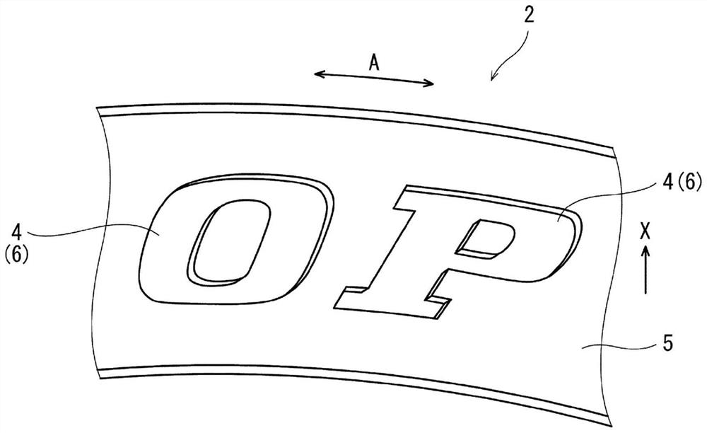
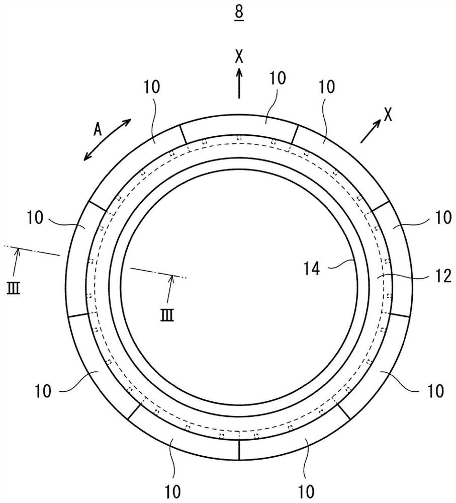
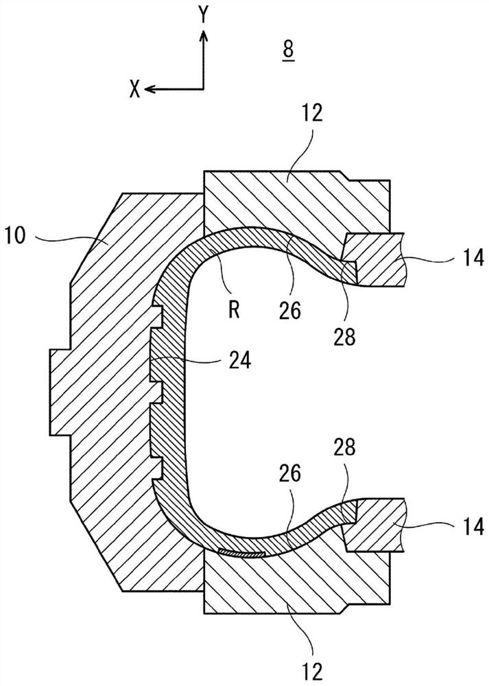
[0060] In the method of (1)-(4) above, formed figure 2 and 3 The cavity face of the side plate shown. The cavity surface of the side plate has a convex portion for forming characters on the tire. In the step (1) above, a base material made of steel is prepared. In the step (2) above, the base cavity surface is formed by lathe processing. In the step (3) above, an iron alloy layer is formed on the base cavity surface by electroplating. The iron content of this iron alloy was 99% by mass. The surface area of ​​the layer of iron alloy is 15% of the surface area of ​​the base cavity face. In the step (4) above, the iron alloy layer is cut by engraving to form protrusions for forming characters on the tire. Thus, the cavity surface is formed.


PUM


Abstract

Provided are a method for manufacturing a tire mold and a method for manufacturing a tire, with which it is possible to efficiently manufacture a mold capable of manufacturing a tire having an excellent appearance. The present invention relates to a method for manufacturing a mold (8) for manufacturing a tire (2) having a concave portion (6) recessed from a reference surface on the surface thereof. The method includes the steps of: (A) forming a base cavity surface (20) for forming the reference surface without the concave portion (6); (B) forming a metal layer (22) in a region of the base cavity surface (20) containing a position corresponding to the recess (6); and (C) cutting the metal layer (22) to form a convex portion (16) having a shape corresponding to the concave portion (6).

Description

technical field [0001] The present invention relates to a method for manufacturing a tire mold and a method for manufacturing a tire. Background technique [0002] Usually, characters and marks are engraved on the surface of the tire. These characters and marks are often formed as recesses that are recessed from the reference plane of the tire. In the mold used to manufacture the tire, the cavity surface has convex portions for forming the concave portions. [0003] Since the shapes of characters and marks are complicated, an engraving machine is usually used for forming the convex portion. The part other than the convex part was chipped off from the part where the cavity surface was formed on the surface of the base material for a mold. The remaining part after cutting becomes a convex part. However, generally, the area where characters and marks exist is small. In this method, the area to be cut by the engraving machine is large, and therefore, the processing time of ...

Claims


Application Information

Patent Timeline
Patent Type & Authority Applications(China)
IPC IPC(8): B29C33/38B29D30/08
CPCB29C33/3842B29D30/08
Inventor 楠智明
Owner SUMITOMO RUBBER IND LTD
Why Eureka
Try Eureka